Text Solution
Verified by Experts


Topper's Solved these Questions
Similar Questions
Explore conceptually related problems
CBSE COMPLEMENTARY MATERIAL-UNIT–III & UNIT–IV MAGNETIC EFFECTS OF CURRENT AND MAGNETISM & E.M.I. AND ALTERNATING CURRENT-(NUMERICALS)
- Two moving coil metres M(1) and M(2) have the following particular R(1...
Text Solution
|
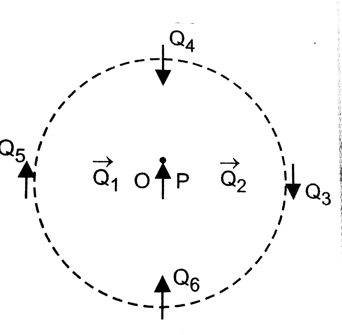
- Figure shows a small magnetised needle P placed at a point O. The arro...
Text Solution
|
- Figure shows a small magnetised needle P placed at a point O. The arro...
Text Solution
|
- Figure shows a small magnetised needle P placed at a point O. The arro...
Text Solution
|
- In the circuit, the current is to be measured. What is the value of th...
Text Solution
|
- In the circuit shown in figure, the current is to measured. What is th...
Text Solution
|
- In the circuit, the current is to be measured. What is the value of th...
Text Solution
|
- An element dvecl=dxhati (where dx=1cm) is placed at the origin and car...
Text Solution
|
- A straight wire of mass 200 g and length 1.5 m carries a current of 2 ...
Text Solution
|
- A rectangular loop of sides 25 cm and 10 cm carrying current of 15A is...
Text Solution
|
- In a chamber, a uniform magnetic field of 6*5G(1G=10^-4T) is maintaine...
Text Solution
|
- In a chamber, a uniform magnetic field of 6*5G(1G=10^-4T) is maintaine...
Text Solution
|
- The horizontal and veritical components of eaths's field at a place ar...
Text Solution
|
- Following figure shows the path of an electron that passes through two...
Text Solution
|
- In a series C–R circuit, applied voltage is V = 110 sin 314t volt. Wha...
Text Solution
|
- Magnetic flux linked with each turn of a 25 turns coil is 6 milliweber...
Text Solution
|
- The current through an inductive circuit of inductance 4mH is i = 12 c...
Text Solution
|
- The current through an inductive circuit of inductance 4mH is i = 12 c...
Text Solution
|
- A power transmission line feeds input power at 2400 V to a step down t...
Text Solution
|
- The magnetic flux linked with a closed circuit of resistance 8Omega va...
Text Solution
|