Home
Class 12
PHYSICS
In the circuit diagram find the potentia...

In the circuit diagram find the potential difference across the plates of capacitor C

A

`I_(1) gt I_(2) `

B

`I_(1) lt I_(2)`

C

`V_(C) gt V'_(C)`

D

`V_(C) lt V'_(C)`

Text Solution

Verified by Experts

The correct Answer is:
B, C

(b,c): Current flowing in circuit can be written as follows :
`I= (V)/(sqrt(R^(2)+((1)/(omegaC))^(2)))`
Voltage across capacitor can be written as follows :
`V_(C) = Ixx(I)/(omegaC)`
`implies V_(C) = (V)/(sqrt(R^(2)+((1)/(omegaC))^(2)))xx(1)/(omegaC)`
`implies V_(C)= (V)/(sqrt((RomegaC)^(2)+1))`
On insertion of dielectric slab capacitance increases and due to this current inreases and voltage across capacitor decreases . Hence options (b)and (c ) are correct.
Promotional Banner

Topper's Solved these Questions

  • ALTERNATING CURRENT

    MODERN PUBLICATION|Exercise COMPETITION FILE D. MULTIPLE CHOICE QUESTIONS|13 Videos
  • ALTERNATING CURRENT

    MODERN PUBLICATION|Exercise COMPETITION FILE ASSERTION REASON TYPE QUESTIONS|10 Videos
  • ALTERNATING CURRENT

    MODERN PUBLICATION|Exercise COMPETITION FILE JEE (ADVANCED ) FOR IIT ENTRANCE|4 Videos
  • ATOMS

    MODERN PUBLICATION|Exercise Chapter Practice Test|16 Videos

Similar Questions

Explore conceptually related problems

Find the potential difference across C_2.

A capacitor of capacity 2muF is changed to a potential different of 12V . It is then connected across an inductor of inductance 0.6mH What is the current in the circuit at a time when the potential difference across the capacitor is 6.0V ?

A capacitor of capacity 2 muF is charged to a potential difference of 12 V . It is then connected across an inductor of inductance 6 mu H . What is the current (in A ) in the circuit at a time when the potential difference across the capacitor is 6.0 V ?

A capacitor only is connected to an AC source. What will be the phase difference between the current flowing in the circuit and the potential difference between the plates of the capacitor?

In the given circuit diagram find the potential difference across 2 Omega resistance (in volts).

Three capacitors of capacitance 1 muF, 2muF and 3 muF are connected in series and a potential difference of 11 V is applied across the combination. Then, the potential difference across the plates of 1 muF capacitor is

In the circuit diagram given below, the value of the potential difference across the plates of the capacitors are. .

In the circuit shown, the potential difference across the 3muF capacitor is V and the equivalent capacitance between A and B is C Then:

MODERN PUBLICATION-ALTERNATING CURRENT -COMPETITION FILE C. MULTIPLE CHOICE QUESTIONS
  1. There is an AC source of rms voltage 200 V and frequency 50 Hz. When t...

    Text Solution

    |

  2. The reactance of a circuit is zero. It is possible that the circuit co...

    Text Solution

    |

  3. L, C and R represent the physical quantities inductance, capacitance a...

    Text Solution

    |

  4. The SI unit of inductance the Henry can not be written as :

    Text Solution

    |

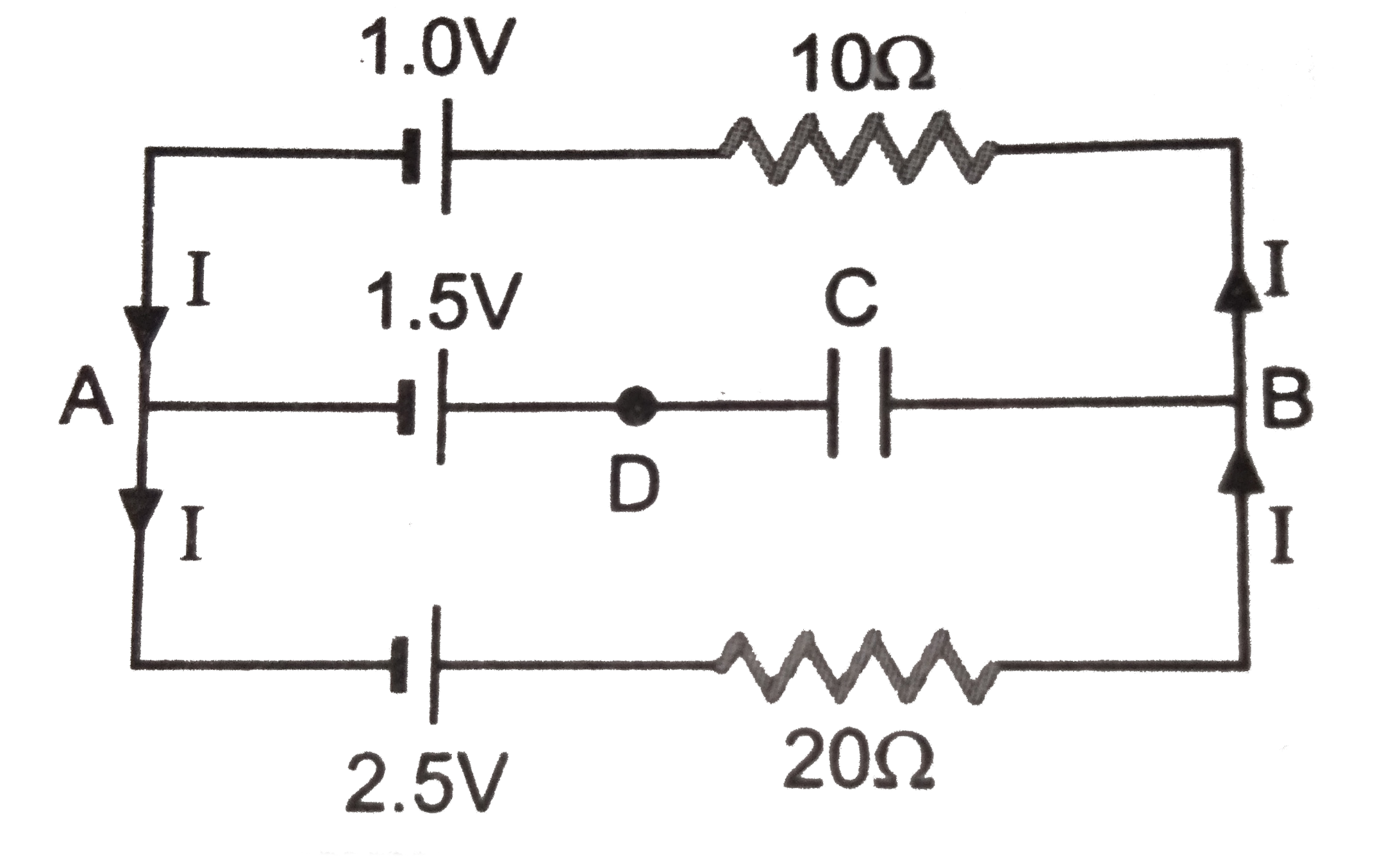
  5. In the circuit diagram find the potential difference across the plates...

    Text Solution

    |

  6. In an AC series circuit, the instanctaneous current is zero when the i...

    Text Solution

    |

  7. Name the device which converts mechanical energy into electrical energ...

    Text Solution

    |

  8. There is one long straight conductor carrying current which is kept al...

    Text Solution

    |

  9. An inductor-coil having some resistance is connected to an AC source. ...

    Text Solution

    |

  10. A constant current I is maintained in a solenoid. Which of lthe follo...

    Text Solution

    |

  11. A sereis R-C circuit is connected to AC voltage source. Consider two c...

    Text Solution

    |

  12. In the given circuit, the AC source has omega = 100 rad/s. considering...

    Text Solution

    |

  13. Two metallic rings A and B, identical in shape and size but having dif...

    Text Solution

    |

  14. In the circuit shown, L = 1 mu H, C = 1 muF and R = 1 kOmega they are...

    Text Solution

    |

  15. The instantaneous voltages at three terminals marked X, Y and Z are gi...

    Text Solution

    |

  16. At time t = 0. terminal A in the circuit shown in the figure is connec...

    Text Solution

    |

  17. In the figure below, the switches S(1) and S(2) are closed simultaneou...

    Text Solution

    |