A
B
C
D
Text Solution
Verified by Experts
The correct Answer is:


Topper's Solved these Questions
ELECTRIC CURRENT AND CIRCUIT
CENGAGE PHYSICS|Exercise Multiple Correct|16 VideosELECTRIC CURRENT AND CIRCUIT
CENGAGE PHYSICS|Exercise Comprehension|35 VideosELECTRIC CURRENT AND CIRCUIT
CENGAGE PHYSICS|Exercise Subjective|29 VideosELECTRIC CURRENT & CIRCUITS
CENGAGE PHYSICS|Exercise Kirchhoff s law and simple circuits|15 VideosELECTRIC FLUX AND GAUSS LAW
CENGAGE PHYSICS|Exercise MCQ s|38 Videos
Similar Questions
Explore conceptually related problems
CENGAGE PHYSICS-ELECTRIC CURRENT AND CIRCUIT-Single Correct
- In the circuit in fig. If no current flows through the galvanometer wh...
Text Solution
|
- A capacitor of capacitance C has charge Q. it is connected to an ident...
Text Solution
|
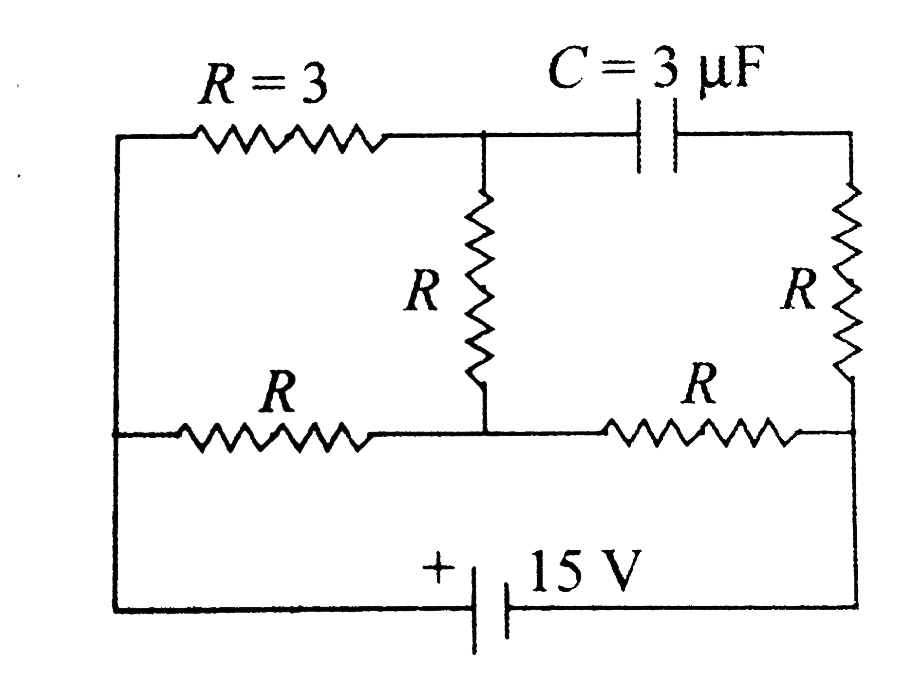
- In the circuit shown in fig. the cell is ideal with emf 15V. Each resi...
Text Solution
|
- The temperature coefficient of resistance of conductor varies as alph...
Text Solution
|
- A straight conductor of uniform cross section carries a time varying c...
Text Solution
|
- Sixteen resistor, each resistane 16 Omega are connected in the circuit...
Text Solution
|
- The circuit diagram shown in the figure consist of a large number of e...
Text Solution
|
- The resistance of all the wires between any two adjacent dots is R. Th...
Text Solution
|
- There is an infinite wire grid with cells in the form of equilateral t...
Text Solution
|
- For the circuit shown in fig. the equivalent resistance between A and ...
Text Solution
|
- ABCD is a square where each side is a uniform wire of resistance 1Omeg...
Text Solution
|
- A capacitor is charged to a certain potential and then allowed to disc...
Text Solution
|
- Two capacitors C1 and C2 (C1 gt C2) are charged separtately to same po...
Text Solution
|
- Under what condition, the current passing through the resistance R can...
Text Solution
|
- In the circuit shown switch S is closed at t=0. Let i1 and i2 be the c...
Text Solution
|
- To get maximum current through a resistance of 2.5Omega, one can use ...
Text Solution
|
- In the given circuit, with steady current, the potential of point A mu...
Text Solution
|
- If the potential difference between A and D is V, what will be potenti...
Text Solution
|
- The current enters at A and leaves at F. The values of some resistance...
Text Solution
|
- The current enters at A and comes out at D. Some of the resistance are...
Text Solution
|