Home
Class 12
PHYSICS
Charge flow through the battery after cl...

Charge flow through the battery after closing the switch is (initially all capacitors are unxharged) :

A

`20 mC`

B

`30 mC`

C

`120 mC`

D

`150 mC`

Text Solution

Verified by Experts

Promotional Banner

Topper's Solved these Questions

  • NUCLEAR PHYSICS

    RESONANCE|Exercise Advanced level solutions|16 Videos
  • SEMICONDUCTORS

    RESONANCE|Exercise Exercise 3|88 Videos

Similar Questions

Explore conceptually related problems

The current through the battery just after the switch S is Closed is (the capacitors are initially uncharged )

(i) Find the total charge flown through the battery in the arrangement shown in figure after switch S is closed (initially all the capacitors are uncharged). (ii) Find out final charge on each capacitor.

Consider the situation shown in the figure. The switch S is open for a long time and then closed and again steady state reached then (a) Find the charge flown through the battery after the switch S is closed. (b) Find the charge flown through the switch S from B to A. (c) Find the work done by the battery after the switch S is closed. (d) Find the change in energy stored in the system of capacitors. (e) Find the heat developed in the system after the switch S is closed.

Find the current passing through battery immediately after key (K) is closed. It is given that initially all the capacitors are uncharged. (Given that R=6Omega and C=4muF)

Six capacitors each of capacitance 'C' is connected as shown in the figure and initially all the capacitors are uncharged . Now a battery of emf = epsilon is connected. How much charge will flow through the battery if the switch is on :

Assertion : The switch S shown in the figure is closed at t = 0 . Initial current flowing through battery is (E)/(R + r) Reason : Initially capacitor was uncharged, so resistance offered by capacitor at t = 0 is zero

Find current through battery when switch is closed.

Find charge supplied by the cell after the switch is closed.

Find the current through the battery (i) just after the switch is closed. (ii) long after the switch has been closed.

For the arrangement shown in the figure, the switch is closed at t = 0 . C_2 is initially uncharged while C_1 has a charge of 2muC (a) Find the current comingn out of the battery just after the switch is closed. (b) Find the charge on the capacitors in the steady state condition.

RESONANCE-REVISION DPP-All Questions
  1. If the cell of emf 5 volt shown in the figure gives a power of 10W. Q,...

    Text Solution

    |

  2. The time when the across the resistor drops to nearly 37% of the value...

    Text Solution

    |

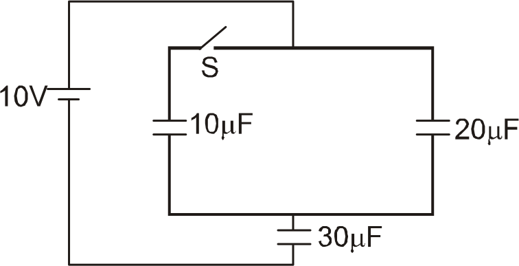
  3. Charge flow through the battery after closing the switch is (initially...

    Text Solution

    |

  4. Electric current through 400 Omega resistor is :

    Text Solution

    |

  5. Two coaxial long solenoids of equal length have current, i(1), i(2), n...

    Text Solution

    |

  6. Two cells of emf epsilon(1) and epsilon(2)(epsilon(2) lt epsilon(1)) a...

    Text Solution

    |

  7. In the figure shown capacitors A and B of capacitance C are in steady ...

    Text Solution

    |

  8. In the circuit shown in figure, E1 and E2 are two ideal sources of unk...

    Text Solution

    |

  9. Find the value of R for which no current will flow through 5V battery

    Text Solution

    |

  10. Find the potential difference (inV) between points A and B shown in th...

    Text Solution

    |

  11. A long straight write is carrying current I(1)=2//5A in +z direction. ...

    Text Solution

    |

  12. Magnetic field is uniform and has a magnitude B in the interior of a v...

    Text Solution

    |

  13. A parallel plate capacitor is to be designed with a voltage rating 1 K...

    Text Solution

    |

  14. A loop PQR formed by three identical uniform conducting rods each of l...

    Text Solution

    |

  15. A conducting wire bent in the from of a parabola y^(2)=2x carries a cu...

    Text Solution

    |

  16. A conducting wire is bend into a loop as shown in the figure. The segm...

    Text Solution

    |

  17. A conducting wire is bend into a loop as shown in the figure. The segm...

    Text Solution

    |

  18. The figure shown is part of the circuit at steady state The poten...

    Text Solution

    |

  19. A galvanometer measures current which passes through it. A galanometer...

    Text Solution

    |

  20. Column I gives ertain situtaions situations in which capacitance of a ...

    Text Solution

    |