Home
Class 12
PHYSICS
In the circuit shown in the figure, the ...

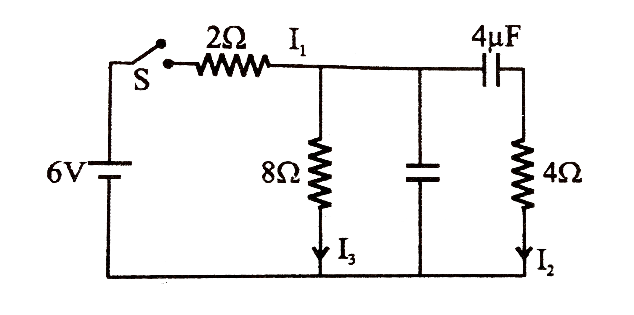
In the circuit shown in the figure, the switch `S` is initially open and the capacitor is initially uncharged. `I_(1),I_(2)` and `I_(3)` represent the current in the resistance `2Omega, 4Omega` and `8Omega` respectively.

A

Just after the switch `S` is closed,
`I_(1) =3A,I_(2) =3A`and `I_(3) = 0`

B

Just after the switch `S` is closed,
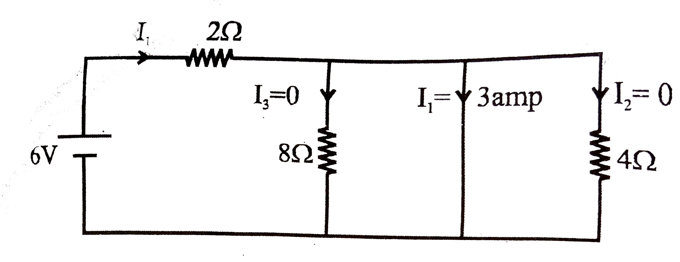
`I_(1) =3A,I_(2) =0`and `I_(3) = 0`

C

long time after the switch `S` is closed,
`I_(1) = 0.6A, I_(2) =0` and `I_(3) = 0`

D

long after the switch `S` is closed,
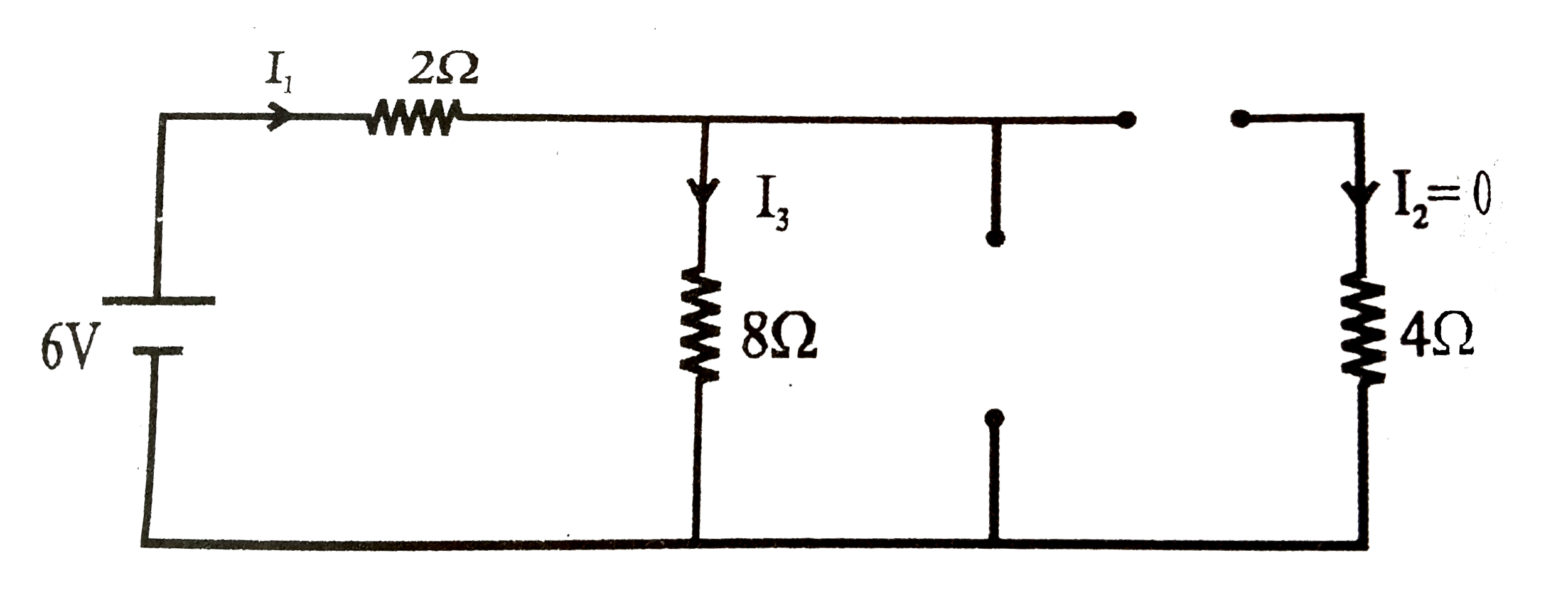
`I_(1) =I_(2) = I_(3) = 0.6A`

Text Solution

Verified by Experts

The correct Answer is:
B

at `t = 0` means just after the switch is closed capacitor acts as short circuit.

After long time capacitor acts as opne circuit.

`I_(1) = I_(3) = 0.6`
Doubtnut Promotions Banner Mobile Dark
|

Similar Questions

Explore conceptually related problems

In the circuit shown in figure-3.355, the current in 1Omega . resistance and charge stored in the capacitor are

In the circuit shown. Initially the capacitor is uncharged. The switch S is closed at time t=0. Then

Knowledge Check

  • In the circuit shown in the figure, the current flowing in 2 Omega resistance

    A
    `1.4A`
    B
    `1.2A`
    C
    `0.4A`
    D
    `1.0A`
  • In the circuit shown, the current in 3Omega resistance is

    A
    `1A`
    B
    `(1)/(7)A`
    C
    `(5)/(7)A`
    D
    `(15)/(7)A`
  • For the circuit shown in the figure, the current in the 4 Omega resistor is

    A
    `0.5A`
    B
    `0.25 A`
    C
    1A
    D
    `1.5 A`
  • Similar Questions

    Explore conceptually related problems

    In the connection shown in the figure the switch K is open and the capacitor is uncharged. Then we close the switch and let the capacitor charge up to the maximum and open the switch again. Then (a) the current through R_(1) be I_(1) immediately after closing the switch, (b) the current through R_(2) be I_(3) immediately after reopening the switch, Find I_(1)/(I_(2) I_(3)) (in ampere^(-1) ) (Use the following data: V_(0)=30VR_(1)=10 K Omega R_(2) = 5 k Omega)

    In the circuit shown in figure-3.171, find current in 4Omega resistance.

    In the circuit shown, the switch 'S' is closed at t =0 . Then capacitor is initially uncharged. Then the current through the resistor R = 8Omega at t = 0.4 xx 10^(-3) sec is (Take e^(-2) = 0.135 )

    In the circuit shown the currents in 4 Omega and 8 Omega resistances are

    In the circuit shown in the figure The steady state currents i_(1)and i_(2) in the coils after the switch S is closed are