Home
Class 12
PHYSICS
The I-V characteristics shown in the fig...

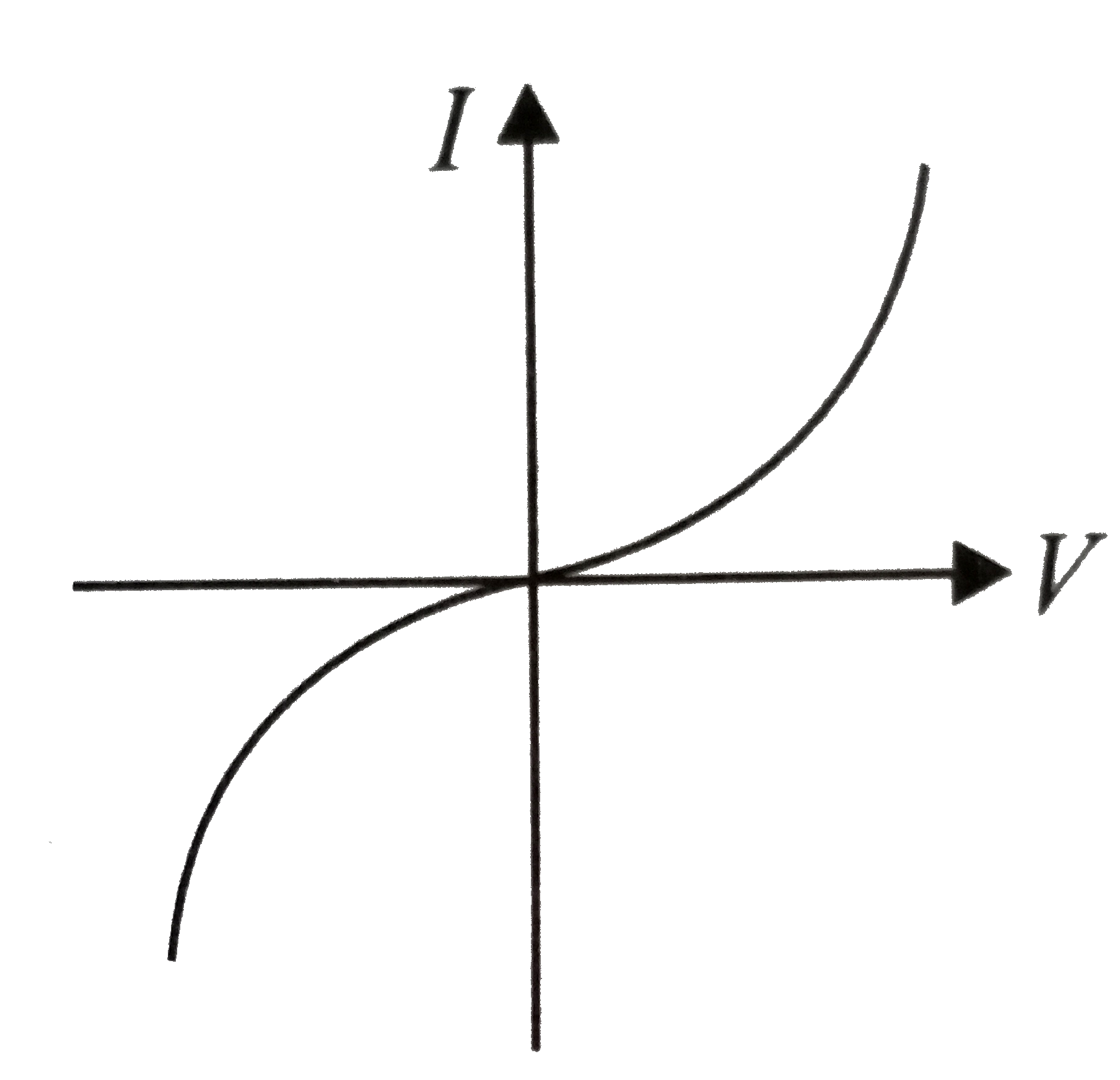
The I-V characteristics shown in the figure represents

A

ohmic conductors

B

non-ohmic conductors

C

insulators

D

superconductors

Text Solution

Verified by Experts

The correct Answer is:
B

The figure is showing I-V characteristics of non-ohmic or non-linear conductors.
Doubtnut Promotions Banner Mobile Dark
|

Topper's Solved these Questions

  • CURRENT ELECTRICITY

    NCERT FINGERTIPS|Exercise Resistivity Of Various Materials|7 Videos
  • CURRENT ELECTRICITY

    NCERT FINGERTIPS|Exercise Temperature Dependence Of Resistivity|7 Videos
  • CURRENT ELECTRICITY

    NCERT FINGERTIPS|Exercise Drift Of Electrons And The Origin Of Resistivity|2 Videos
  • COMMUNITCATION SYSTEMS

    NCERT FINGERTIPS|Exercise HOTS|10 Videos
  • DUAL NATURE OF RADIATION AND MATTER

    NCERT FINGERTIPS|Exercise Assertion And Reason|15 Videos

Similar Questions

Explore conceptually related problems
The resistance of a germanium junction diode, whose V –I characteristics is shown in the figure , will be ( v_k= 0.3 V ) .

The V-I characteristic of a diode is shown in the figure. The ratio of forward to reverse bias resistance is

Knowledge Check

  • The I-V characteristic of an LED is.

    A
    B
    C
    D
  • The current I, potential difference V_(L) across the inductor and potential difference V_(C ) across the capacitor in circuit as shown in the figure are best represented vectorially as

    A
    B
    C
    D
  • For the circuit shown in the figure current I will be

    A
    0.75A
    B
    1A
    C
    1.5A
    D
    0.5A
  • Similar Questions

    Explore conceptually related problems

    For the forward biased diode characteristics shown in the figure, the dynamic resistance at I_(D)= 3 mA will be ………. Omega .

    Which of the plots shown in the figure represents speed (v_n) of the electron in a hydrogen atom as a function of the principal quantum number (n)?

    The x -t graph shown in figure represents

    (i) Name the type of a diode whose characteristics are shown in figure (a) and (b) (ii) What does the point P in fig. (a) represent ? (iii) What does the point P and Q in fig. (b) represent ?

    The output Y of the logic circuit as shown in figure is best represents as