


KCET PREVIOUS YEAR PAPERS-KARNATAKA CET 2017-PHYSICS
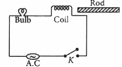
- In the A. C. circuit shown, keeping 'K' pressed, if an iron rod is ins...
Text Solution
|
- A basic communication system consists of (a) Transmitter (b) Info...
Text Solution
|
- A bar magnet is allowed to fall vertically through a copper coil place...
Text Solution
|
- Two spheres of electric charges +2 nC and -8 nC are placed at a distan...
Text Solution
|
- The partlcles emitted 1n the decay of ""(92)^(238)U to ""(92)^(234)U
Text Solution
|
- In the figure shown, if the diode forward voltage drop is 0.2 V, the ...
Text Solution
|
- In Young's double - slit experiment if yellow light is replaced by blu...
Text Solution
|
- A system of 2 capacitors of capacitance 2muF and 4muF is connected in ...
Text Solution
|
- 4 xx 10^(10) electrons are removed from a neutral metal sphere of diam...
Text Solution
|
- Write the SI unit of specific heat of a substance.
Text Solution
|
- A coil of inductive reactance 1// sqrt(3) Omega and resistance 1 Omega...
Text Solution
|
- Which of the following logic gates considered as universal?
Text Solution
|
- Which of the following semi-conducting devices is used as voltage regu...
Text Solution
|
- In metre bridge experiment, with a standard resistance in the right ga...
Text Solution
|
- The susceptibility of a ferromagnetic substance is
Text Solution
|
- For which combination of working temperatures, the efficiency of 'Carn...
Text Solution
|
- The mean energy of a molecule of an ideal gas is
Text Solution
|
- Hydraulic lift works on the basis of
Text Solution
|
- A car moving with a velocity of 20 ms^(-1) is stopped in a distance of...
Text Solution
|
- Of the following graphs, the one that correctly represents the I-V cha...
Text Solution
|