Hertz Experiment : Hertz.s experiment was based on the fact that an oscillating electric charge radiates electromagnetic waves and these waves carry energy which is being supplied at the cost of K.E. of the oscillating charge.
Hertz Apparatus : The experimental arrangement used by Hertz for the production and detection of electromagnetic waves in the laboratory, is shown in fig. His experimental arrangement consists of two metal sheets `P_1 and P_2`. These sheets are connected to a source of very high voltage (ie, an induction coil, which can supply a potential difference of several thousand volts). `S_1 and S_2` are two metal spheres connected to the metal sheets `P_1 and P_2`. The distance between the metal sheets is kept nearly 60 cm and that between the sphere is normally from 2 cm to 2.5 cm.
The two plates `P_1 and P_2` form a capacitor of very low capacitance (C). The circuit containing `P_1 and P_2` (being completed by conducting wire), has also some low value of inductance L. It thus forms an LC circuit. Detector (D) consisting of a coil to the ends of which two other small metal spheres `S._1` and `S._2` are connected.
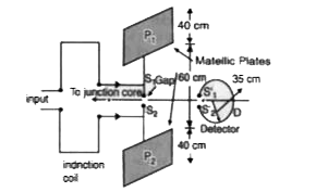
Fig. : Schematic diagram of Hertz Experiment Working of Hertz apparatus : Due to existence of very high voltage, air present in the gap across the plates or spheres `S_1 and S_2` gets ionised. Due to presence of the ions or charged particles, the path between the spheres `S_1 and S_2` become conducting. As a result of this, very high time-varying current flows across the gap between `S_1 and S_2` (as plates `P_1 and P_2` form an LC circuit). Due to this a spark is produced. Since, sheets `P_1 , P_2` form an LC circuit, hence, electromagnetic waves of frequency `f = 1/(2pi) sqrt((1)/(LC))` are radiated .
Function of the detection D : Hertz detected the electromagnetic waves by means of a detector D, kept at suitable distance from the conducting spheres `S_1^1, S_2^1` .Detector D is made of two similar conducting spheres `S_1^1` and `S_2^1` joined to the ends of a coil to form another LC circuit. The frequency of this LC circuit is made equal to the frequency of electromagnetic waves reaching it. The frequency can be adjusted by changing the diameter of the coil of the detector and by changing the distance between `S._1 and S._2`. Hertz placed the detector in such a way that the magnetic lines of force produced by the oscillating electric field across the gap between `S._1 and S._2` are normal to the plane of coil (C). When magnetic lines of force cut the detector coil, an emf is induced in it. Hence, air in between the gap gets ionised. A conducting path becomes available for the induced current to flow across the gap. Thus, the spark is produced between `S._1 and S._2`. Hertz also observed that the spark across the gap was the greatest when `S._1 S._2` were parallel to each other. This clearly established that electromagnetic waves produced were polarised i.e., `vecE` and `vecB` always lie in one plane.


