Text Solution
Verified by Experts


Topper's Solved these Questions
ELECTRICITY
OSWAAL PUBLICATION|Exercise TOPIC-2 ( Long Answer Type Questions )|29 VideosELECTRICITY
OSWAAL PUBLICATION|Exercise NCERT CORNER ( Intext Questions )|23 VideosELECTRICITY
OSWAAL PUBLICATION|Exercise TOPIC-2 ( Short Answer Type Questions -I )|15 VideosLIGHT-REFLECTION AND REFRACTION
OSWAAL PUBLICATION|Exercise NCERT CORNER (TEXTBOOK EXERCISES)|15 Videos
Similar Questions
Explore conceptually related problems
OSWAAL PUBLICATION-ELECTRICITY-TOPIC-2 ( Short Answer Type Questions -II )
- A bulb is rated 5V, 500 mA. Calculate the rated power and resistance o...
Text Solution
|
- Define electric power. An electric motor is rated at 2kW. Calculate th...
Text Solution
|
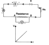
- State Ohm's Law. Draw a circuit diagram to verify this law indicating...
Text Solution
|
- Give reason for the following : Why are copper and aluminium wires u...
Text Solution
|
- Explain the following Why is tungsten used almost exclusively for fi...
Text Solution
|
- Give reason for the Why ie lead-tin alloy used for fuse wires ?
Text Solution
|
- V-1 graph for a conductor is as shown in figure. (i) What do yo...
Text Solution
|
- Show four different ways in which three resistors of Rohm each may be ...
Text Solution
|
- Can you run electric geysor with power rating 2 kW, 220 V on a 5 A lin...
Text Solution
|
- a] Derive an expression for the equivalent resistance of three resisto...
Text Solution
|
- Electrical reslstivities of some substances, In ohm- meter, at 20^(@) ...
Text Solution
|
- Electrical reslstivities of some substances, In ohm- meter, at 20^(@) ...
Text Solution
|
- Electrical reslstivities of some substances, In ohm- meter, at 20^(@) ...
Text Solution
|
- In the above circuit, connect a nichrome wire of length ' between poin...
Text Solution
|
- What is meant by saying that the potential difference between two poin...
Text Solution
|
- Two devices of ratings 44W, 200V and 11W, 220V are connected in series...
Text Solution
|
- Obtain an expression for equivalent resistance of two resistors connec...
Text Solution
|
- Semi-conductors are certain type, of metals which allow only partial c...
Text Solution
|
- A bulb is rated at 200V -40W. What is its resistantt ? 5 such bulbs ar...
Text Solution
|
- Three resistors of 10 Omega, 15 Omega and 20 Omega are connected in s...
Text Solution
|