A student in a lab took a coil and connected it to a `12 VDC` source. He measures the steady state current in the circuit to be `4 A`. He then replaced the `12 VDC` source by a `12V,(omega=50rad/s)AC` source and observes that the reading in the `AC` ammeter is `2.4 A`. He then decides to connect a `2500 muF` capacitor in series with the coil and calculate the average power developed in the circuit. Further he also decides to study the variation in current in the circuit (with the capacitor and the battery in series).
Which of the following graph roughly matches the variation of current in the circuit (with the coil and capacitor connected in the series) when the angulr frequency is decreased from 50 rad/s to 25 rad/s?
Which of the following graph roughly matches the variation of current in the circuit (with the coil and capacitor connected in the series) when the angulr frequency is decreased from 50 rad/s to 25 rad/s?
A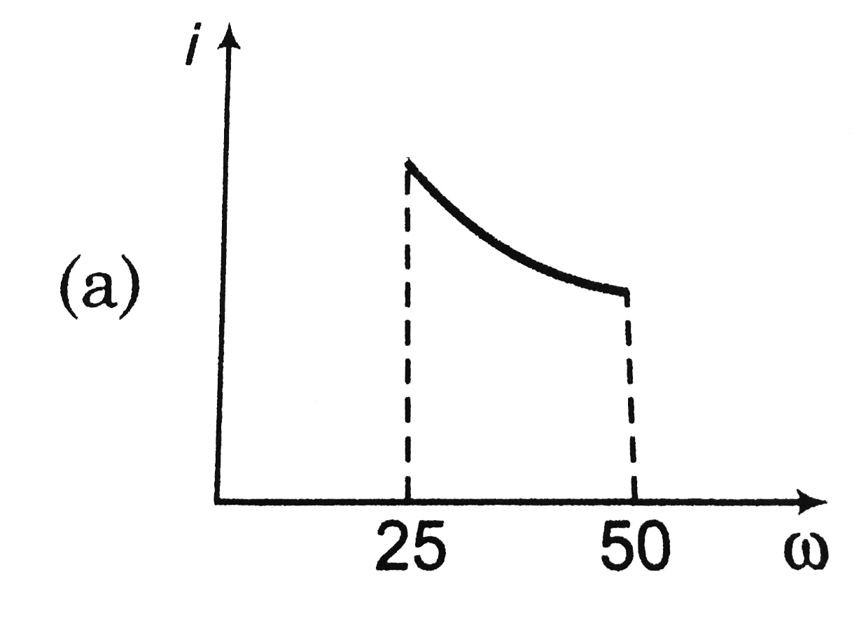
B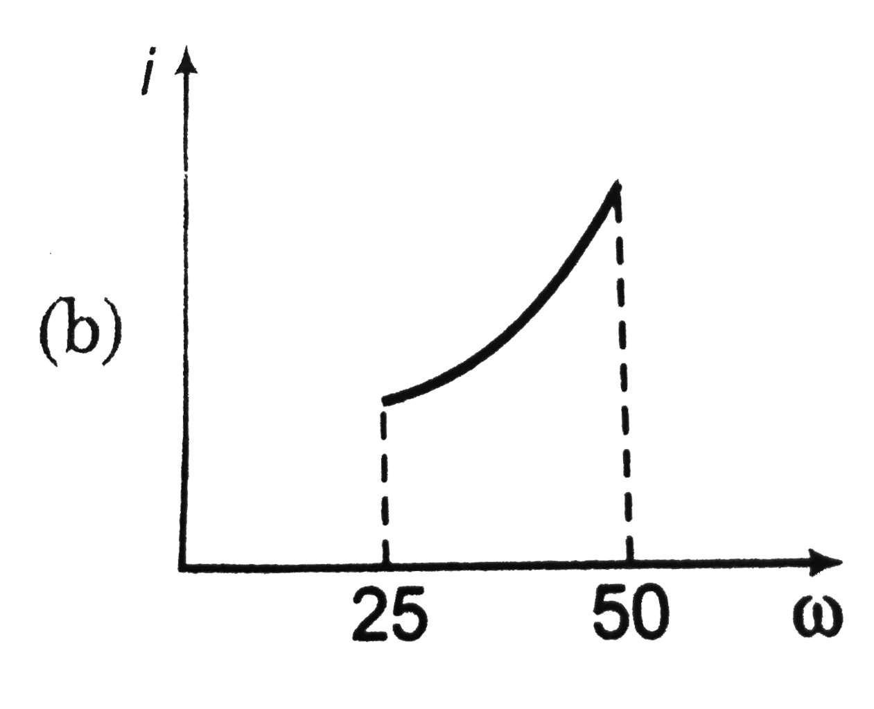
C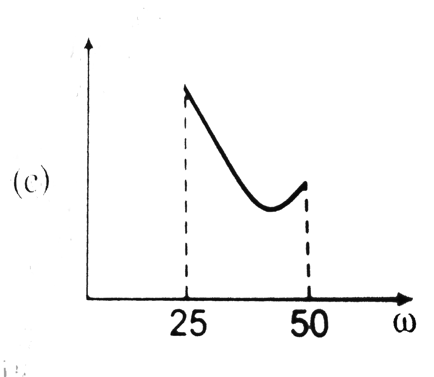
D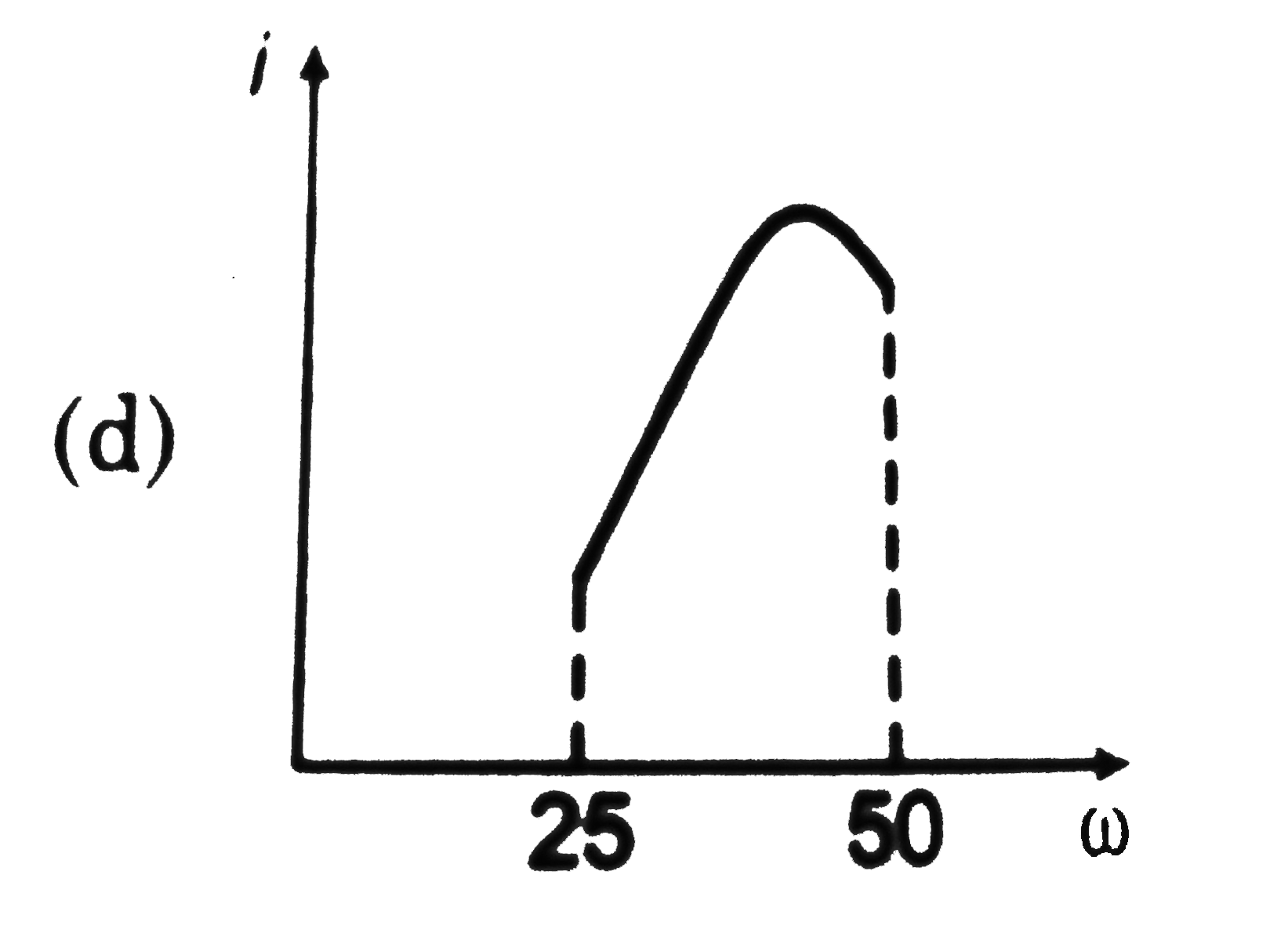
Text Solution
AI Generated Solution
The correct Answer is:
To solve the problem, we need to analyze the behavior of the circuit when a capacitor is added in series with an inductor (coil) and how the current varies with a change in angular frequency. Here’s a step-by-step breakdown:
### Step 1: Understand the Circuit Components
- The circuit consists of a coil (inductor) and a capacitor connected in series.
- The initial measurements were taken with a DC source and then with an AC source at an angular frequency of \( \omega = 50 \, \text{rad/s} \).
### Step 2: Calculate the Impedance of the Circuit
1. **Impedance Formula**: For a series RLC circuit, the impedance \( Z \) is given by:
\[
Z = \sqrt{R^2 + (X_L - X_C)^2}
\]
where \( R \) is the resistance, \( X_L \) is the inductive reactance, and \( X_C \) is the capacitive reactance.
2. **Given Values**:
- From the DC circuit, the resistance \( R \) can be calculated using Ohm's law:
\[
R = \frac{V}{I} = \frac{12 \, \text{V}}{4 \, \text{A}} = 3 \, \Omega
\]
- The AC current is given as \( 2.4 \, \text{A} \) at \( \omega = 50 \, \text{rad/s} \).
3. **Calculate \( X_L \)**:
- The inductive reactance \( X_L \) can be calculated using:
\[
I = \frac{V}{Z} \implies Z = \frac{V}{I} = \frac{12 \, \text{V}}{2.4 \, \text{A}} = 5 \, \Omega
\]
- Rearranging the impedance formula gives:
\[
5 = \sqrt{3^2 + (X_L - X_C)^2}
\]
- Solving for \( (X_L - X_C) \):
\[
5^2 = 9 + (X_L - X_C)^2 \implies 25 - 9 = (X_L - X_C)^2 \implies (X_L - X_C)^2 = 16 \implies |X_L - X_C| = 4
\]
### Step 3: Calculate Capacitive Reactance
1. **Capacitive Reactance**:
- The capacitive reactance \( X_C \) is given by:
\[
X_C = \frac{1}{\omega C}
\]
- Given \( C = 2500 \, \mu F = 2500 \times 10^{-6} \, F \):
- At \( \omega = 50 \, \text{rad/s} \):
\[
X_C = \frac{1}{50 \times 2500 \times 10^{-6}} = \frac{1}{0.125} = 8 \, \Omega
\]
### Step 4: Analyze the Effect of Decreasing Angular Frequency
1. **Decrease \( \omega \)**:
- When \( \omega \) decreases from \( 50 \, \text{rad/s} \) to \( 25 \, \text{rad/s} \), \( X_C \) increases:
\[
X_C = \frac{1}{25 \times 2500 \times 10^{-6}} = \frac{1}{0.05} = 20 \, \Omega
\]
2. **Calculate New Impedance**:
- The new impedance \( Z \) when \( \omega = 25 \, \text{rad/s} \):
\[
Z = \sqrt{R^2 + (X_L - X_C)^2}
\]
- Since \( X_L - X_C \) will now be \( 4 - 20 = -16 \):
\[
Z = \sqrt{3^2 + (-16)^2} = \sqrt{9 + 256} = \sqrt{265} \approx 16.28 \, \Omega
\]
### Step 5: Calculate the New Current
- The new current \( I \) can be calculated using:
\[
I = \frac{V}{Z} = \frac{12 \, \text{V}}{16.28 \, \Omega} \approx 0.737 \, A
\]
### Step 6: Graphical Representation
- As the angular frequency decreases, the current decreases due to the increase in capacitive reactance, resulting in a higher impedance.
- The graph that represents the current variation as \( \omega \) decreases from \( 50 \, \text{rad/s} \) to \( 25 \, \text{rad/s} \) would show a decreasing trend in current.
### Conclusion
The correct graph that matches the variation of current in the circuit when the angular frequency is decreased from \( 50 \, \text{rad/s} \) to \( 25 \, \text{rad/s} \) is the one showing a decrease in current.
To solve the problem, we need to analyze the behavior of the circuit when a capacitor is added in series with an inductor (coil) and how the current varies with a change in angular frequency. Here’s a step-by-step breakdown:
### Step 1: Understand the Circuit Components
- The circuit consists of a coil (inductor) and a capacitor connected in series.
- The initial measurements were taken with a DC source and then with an AC source at an angular frequency of \( \omega = 50 \, \text{rad/s} \).
### Step 2: Calculate the Impedance of the Circuit
1. **Impedance Formula**: For a series RLC circuit, the impedance \( Z \) is given by:
...


Topper's Solved these Questions
Similar Questions
Explore conceptually related problems
A student in a lab took a coil and connected it to a 12 VDC source. He measures the steady state current in the circuit to be 4 A . He then replaced the 12 VDC source by a 12V,(omega=50rad//s)AC source and observes that the reading in the AC ammeter is 2.4 A . He then decides to connect a 2500 muF capacitor in series with the coil and calculate the average power developed in the circuit. Further he also decides to study the variation in current in the circuit (with the capacitor and the battery in series). The value of resistance of the coil calculated by the student is
A student in a lab took a coil and connected it to a 12 VDC source. He measures the steady state current in the circuit to be 4 A . He then replaced the 12 VDC source by a 12V,(omega=50rad//s)AC source and observes that the reading in the AC ammeter is 2.4 A . He then decides to connect a 2500 muF capacitor in series with the coil and calculate the average power developed in the circuit. Further he also decides to study the variation in current in the circuit (with the capacitor and the battery in series). The power developed in te circuit when the capcitor of 2500 muF is connected in sereis with the coil is
A 0.21 H inductor and a 12 Omega resistance are connected in series to a 220 V, 50 Hz ac source. The current in the circuit is
A resistance is connected to a n AC source. If a capacitor is induced in the series cirucit, the average power absorbed by the resistance
A 100W bulb is connected to an AC source of 220V , 50Hz . Then the current flowing through the bulb is
A current of 4A flows in a coil when connected to a 12V DC source. If the same coil is connected to a 12V, 50 rad//s AC source, a current of 2.4A flows in the circuit. Determine the inductance of the coil. Also, find the power developed in the circuit if a 2500muF capacitor is connected in series with the coil.
A current of 4A flows in a coil when connected to a 12V DC source. If the same coil is connected to a 12V, 50 rad//s AC source, a current of 2.4A flows in the circuit. Determine the inductance of the coil. Also, find the power developed in the circuit if a 2500muF capacitor is connected in series with the coil.
A current of 4A flows in a coil when connected to a 12V DC source. If the same coil is connected to a 12V, 50 rad//s AC source, a current of 2.4A flows in the circuit. Determine the inductance of the coil. Also, find the power developed in the circuit if a 2500muF capacitor is connected in series with the coil.
A long solenoid connected to a 12V DC source passes a steady current of 2 A. When the solenoid is connected to an AC source of 12V at 50 Hz, the current flowing is 1A. Calculate inductance of the solenoid.
A 0.21 H inductor and a 12 ohm resistance are connected in series to a 220 V . 50 Hz ac source. Calculate the current in the circuit and the phase angle between the current and the source voltage.
DC PANDEY ENGLISH-ALTERNATING CURRENT-Level 2 Comprehension
- A student in a lab took a coil and connected it to a 12 VDC source. He...
Text Solution
|
- A student in a lab took a coil and connected it to a 12 VDC source. He...
Text Solution
|
- A student in a lab took a coil and connected it to a 12 VDC source. He...
Text Solution
|
- It is known to all of you that the impedance of a circuit is dependent...
Text Solution
|
- It is known to all of you that the impedance of a circuit is dependent...
Text Solution
|
- It is known to all of you that the impedance of a circuit is dependent...
Text Solution
|