A
B
C
D
Text Solution
Verified by Experts
The correct Answer is:


Topper's Solved these Questions
CURRENT ELECTRICITY
RESONANCE ENGLISH|Exercise Exrcies-3(PART-1)|22 VideosCURRENT ELECTRICITY
RESONANCE ENGLISH|Exercise Exrcies-3(PART-2)|23 VideosCURRENT ELECTRICITY
RESONANCE ENGLISH|Exercise Exercise-2 (Part-3)|22 VideosCOMMUNICATION SYSTEMS
RESONANCE ENGLISH|Exercise Exercise 3|13 VideosDAILY PRACTICE PROBLEM
RESONANCE ENGLISH|Exercise DPP.No.71|1 Videos
Similar Questions
Explore conceptually related problems
RESONANCE ENGLISH-CURRENT ELECTRICITY-Exercise-2 (Part-4)
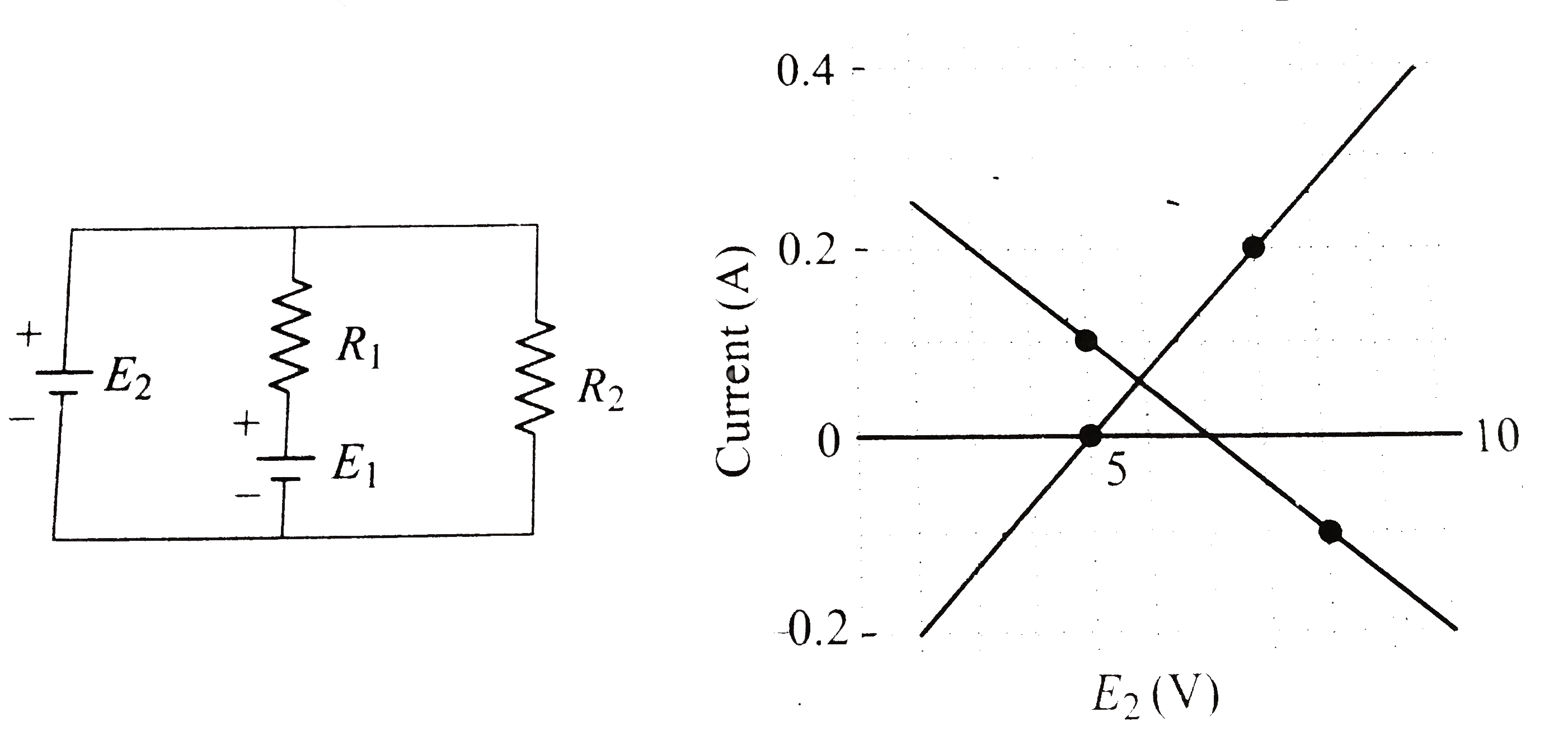
- In the circuit given in the figure, both batteries are ideal . Emf E1 ...
Text Solution
|
- In the circuit given in the figure, both batteries are ideal . Emf E1 ...
Text Solution
|
- In the circuit given in the figure, both batteries are ideal . Emf E1 ...
Text Solution
|
- A network of resistance is constructed with R(1)" and R(2) as shown in...
Text Solution
|
- A network of resistance is constructed with R1 and R2 as shown in fig....
Text Solution
|
- A nichrome wire AB, 100 cm long and of uniform cross section cross sec...
Text Solution
|
- A nichrome wire AB, 100 cm long and of uniform cross section cross sec...
Text Solution
|
- In the adjacent circuit a resisttance R is used. Initially with 'wire...
Text Solution
|
- A metal plate 0.04m^(2) in area is lying on a liquid layer of thicknes...
Text Solution
|
- The reading of pressure-meter fitted in a closed pipe is 4.5 xx 10^(5)...
Text Solution
|
- The following combination are concerned with experiments of the charac...
Text Solution
|
- The deflection in a moving coil galvanometer is:
Text Solution
|