A
B
C
D
Text Solution
Verified by Experts
The correct Answer is:


Topper's Solved these Questions
ELECTROMAGNETIC INDUCTION
RESONANCE ENGLISH|Exercise Exercis-2 PART 2|17 VideosELECTROMAGNETIC INDUCTION
RESONANCE ENGLISH|Exercise Exercis-2 PART 3|10 VideosELECTROMAGNETIC INDUCTION
RESONANCE ENGLISH|Exercise Exercis-1 PART 2|51 VideosELECTRODYNAMICS
RESONANCE ENGLISH|Exercise Advanced level problems|31 VideosELECTROSTATICS
RESONANCE ENGLISH|Exercise HLP|40 Videos
Similar Questions
Explore conceptually related problems
RESONANCE ENGLISH-ELECTROMAGNETIC INDUCTION-Exercis-2 PART 1
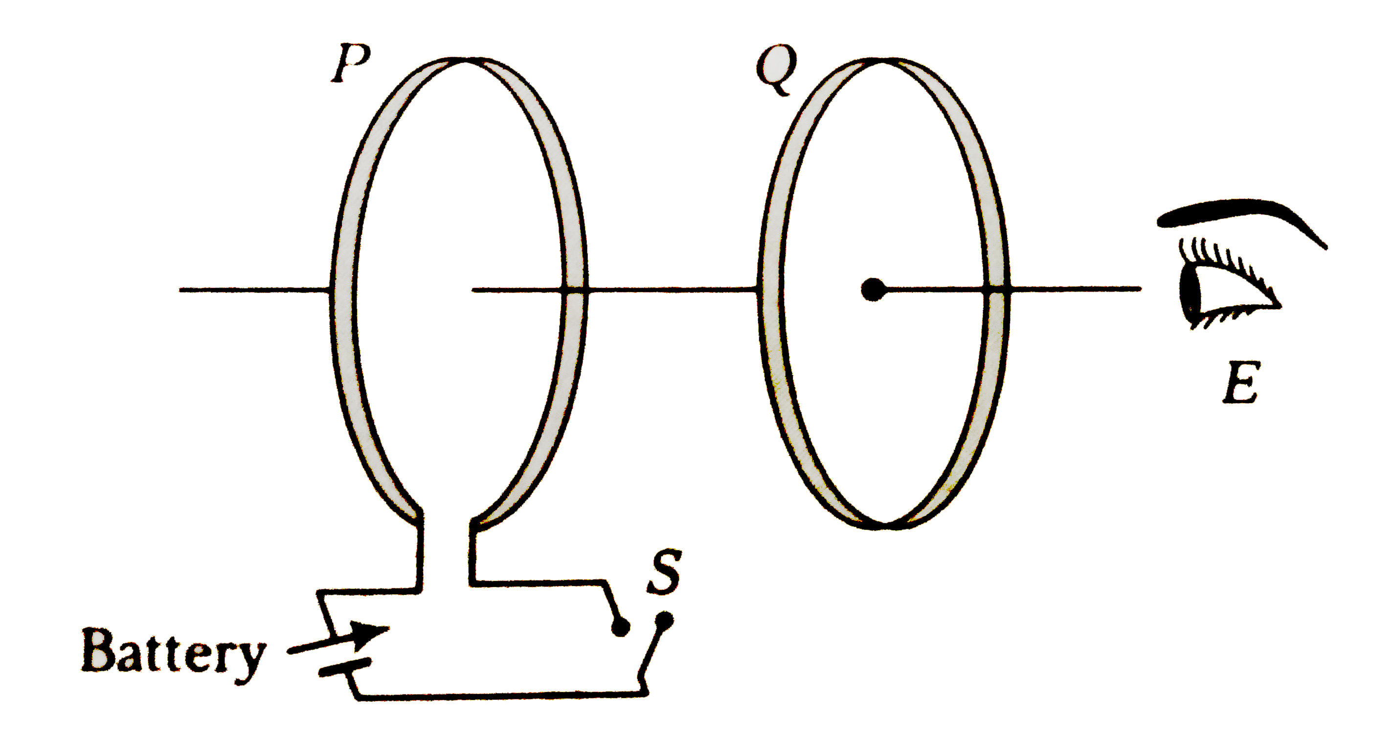
- As shown in figure, P and Q are two co-axial conducting loops separate...
Text Solution
|
- A close loop is placed in a time-varying magnetic field. Electrical po...
Text Solution
|
- Loop A of radius rgtgtR moves toward loop B with a constant velocity V...
Text Solution
|
- Radius of a circular ring is changing with time and the coil is placed...
Text Solution
|
- A triangular loop as shown in the figure is started to being pulled ou...
Text Solution
|
- A metal rod of resistance 20Omega is fixed along diameter of a conduct...
Text Solution
|
- Assume Earth's surface is a conductor with a uniform surface charge de...
Text Solution
|
- A non conducting ring having a charge q uniformly distributed over its...
Text Solution
|
- A uniform magnetic field B=B(0)t (where B(0) is a positive constant) f...
Text Solution
|
- A conducting disc of radius R is placed in a uniform and constant magn...
Text Solution
|
- When the current in a certain inductor coil is 5.0 A and is increasing...
Text Solution
|
- Rate of increment of energy in an inductor with time in series RL circ...
Text Solution
|
- When the current in the portion of the circuit shown in the figure is...
Text Solution
|
- In the circuit shown switch S is connected to position 2 for a long ti...
Text Solution
|