Home
Class 12
PHYSICS
Identify which basic gate, OR, AND and N...

Identify which basic gate, OR, AND and NOT is represented by the circuits in the dotted line boxes 1, 2 and 3 Fig.

Text Solution

Verified by Experts

In dotted line box 1 is a NOT gate
Explanation. Its circuits is as shown in Fig.

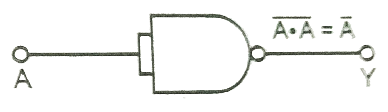
Here `y=bar(A.A)=barA+barA=barA=NOT A`
In dotted line box 2 is an OR gate.
Explanation. Its circuit is as shown in Fig.

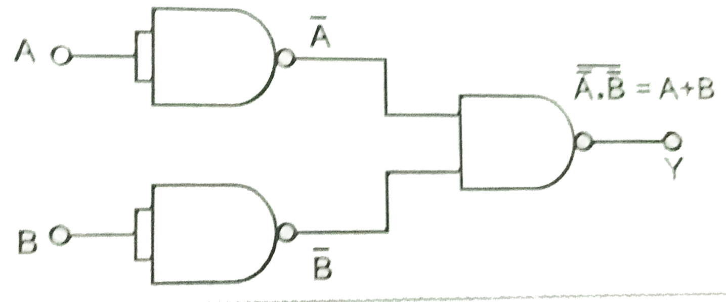
Here, `y=bar(barA.barB)=A+B=A OR B`
(From De-Morgan's Theorem)
In dotted line box 3 is AND gate.
Explanation. Its circuit is as shown in Fig.
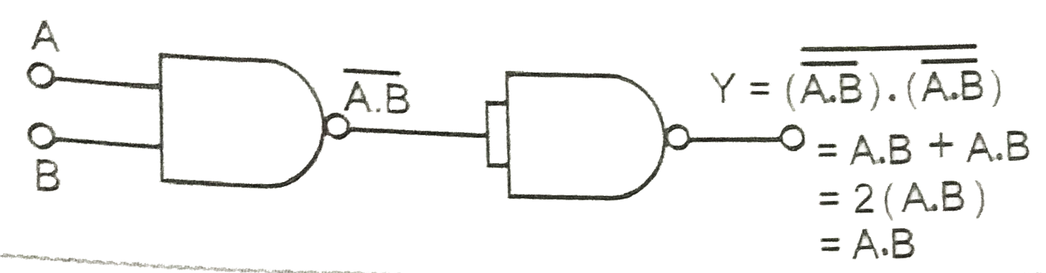
Here, `y=bar((bar(A.B)).bar((A.B))) = A.B+A.B`
Applying de Morgon's theorem
(i) `bar(barC+barD)=C.D (ii) bar(barC.barD)=C+D`
`:. y=A.B+A.B=A.(B+B)=A.B`
`=A AND B. ( :' B+B=B OR B=B)`
Similarrly, we can explain the values of y for other values of A and B in truth table.
Promotional Banner

Topper's Solved these Questions

  • ELECTRONIC DEVICES

    PRADEEP|Exercise SAMPLE PROBLEM|2 Videos
  • ELECTRONIC DEVICES

    PRADEEP|Exercise CONCEPTUAL PROBLEMS|1 Videos
  • ELECTROMAGNETIC WAVES

    PRADEEP|Exercise II Focus multiple choice question|5 Videos
  • ELECTROSTATICS

    PRADEEP|Exercise ASSERTION-REASON TYPE QUESTIONS|2 Videos

Similar Questions

Explore conceptually related problems

Which gate is represented by the given truth table

Which gate is represented by this figure?

Which logic gate is represented by the following truth table?

Name the Gate represented by the following circuit.

Which logic gate is represented by the following truth table ?

Which logic gate is represented by the following combination of logic gates

Which logic gate is represented by the following combination of logic gates ?

Which logic gate is represented by following diagram?

In the circuit shown in fig., the value of I_1+I_2 is