Text Solution
Verified by Experts


Topper's Solved these Questions
ELECTRONIC DEVICES
PRADEEP|Exercise LONG QUESTION ANSWER|2 VideosELECTRONIC DEVICES
PRADEEP|Exercise PROBLEMS FOR PRACTICE|7 VideosELECTRONIC DEVICES
PRADEEP|Exercise HIGHER ORDER THINKING SKILLS|1 VideosELECTROMAGNETIC WAVES
PRADEEP|Exercise II Focus multiple choice question|5 VideosELECTROSTATICS
PRADEEP|Exercise ASSERTION-REASON TYPE QUESTIONS|2 Videos
Similar Questions
Explore conceptually related problems
PRADEEP-ELECTRONIC DEVICES-Exercise
- Find the current through the resistance R in Fig if R =10 Omega and R...
Text Solution
|
- A silicon p-n junction diode whose knee voltage is 0.7 V is connected ...
Text Solution
|
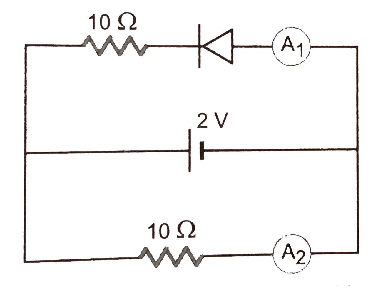
- Assuming that the resistance of the meters are negligible, what will b...
Text Solution
|
- The applied input a.c. to a half wave rectifier is 120 watt. The d.c. ...
Text Solution
|
- Find the average value of d.c. voltage that can be obtained from the h...
Text Solution
|
- In a photo diode the conductivity increases when the material is expos...
Text Solution
|
- In a silicon transistor, a change of 8.0 mA in the emitter current pro...
Text Solution
|
- The current gain for common emitter amplifier is 69. If the emitter cu...
Text Solution
|
- The potential difference across the collector of a transistor, used in...
Text Solution
|
- Output characteristics of an n-p-n transistor in CE configuration is s...
Text Solution
|
- The base current of a transistor is 105 muA and collector current is 2...
Text Solution
|
- In a silicon transistor, base current is changed by 20muA. This result...
Text Solution
|
- The input resistance of a silicon transistor is 665Omega. Its base cur...
Text Solution
|
- A transistor, connected in common emitter configuration, has input res...
Text Solution
|
- A change of 0.2mA in the base current cause a change of 5mA in the col...
Text Solution
|
- A transistor is used in common-emitter mode in an amplifier circuit. I...
Text Solution
|
- For a common emitter transistor amplifier, the audio signal voltage ac...
Text Solution
|
- A full wave rectifier uses two diodes, the internal resistance of each...
Text Solution
|
- An a.c. supply if 230V is applied to a half wave rectifier circuit thr...
Text Solution
|
- A half wave rectifier is used to supply 50V d.c. to a resistance load ...
Text Solution
|