Home
Class 12
PHYSICS
At resonance, V(L) and V(C ) both very m...

At resonance, `V_(L)` and `V_(C )` both very much greater than the applied potential, `V` itself. The quantity factor for an `LCR` circuit in resonance is given by `Q = (X_(L))/(R )`. In pratice, `Q = 200` has been achieved.

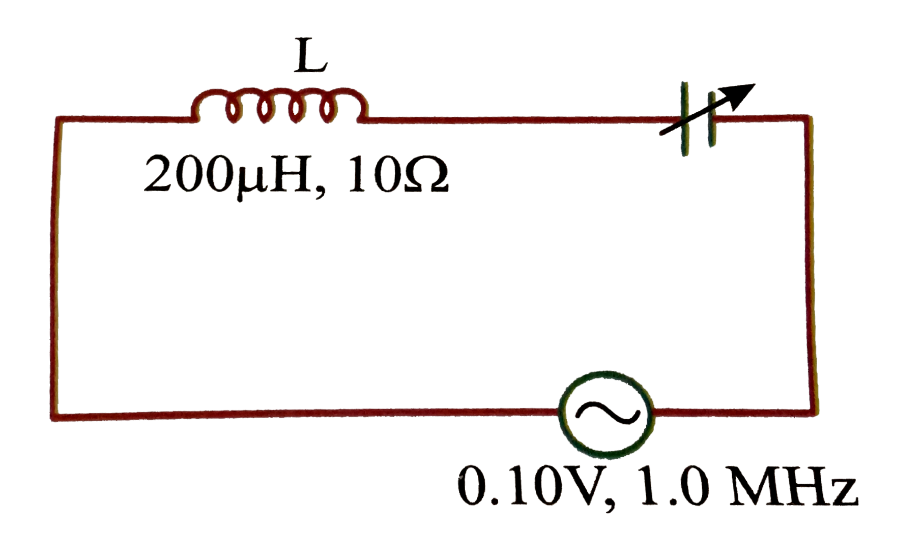
At resonance, the capacitor has been adjusted for
(1). `200 xx 10^(-6) mu F`
(2) `0.00013 mu F`
(3). `0.0012 mu F`
(4). `0.0013 F`
At resonance, the potential difference across the inductance is
(1) `1.3 V`
(2) `13 V`
(3). `0.3 V`
(d) none of these
The potential across the capacitor at resosnance is
(1) `1.3 V`
(2) `13 V`
(3) `lt 13 V`
(4) none of these
The `Q` factor is
(1) `(V_(L))/(V_(C ))`
(2) `(V_(C ))/(V_(L))`
(3) `(V_(C ))/(V)`
(d) `(V_(L))/(V)`
(e) choose the right statement.
(1) `V_(L)+V_(C)` can be greater than `V_("applied")`
(2) `V_(L)+V_(C)=V_("applied")`
(3) `V_(L)+V_(C) lt V_("applied")`
(4) none of these

Text Solution

Verified by Experts

The correct Answer is:
2, 3, 1, (3,4)
Doubtnut Promotions Banner Mobile Dark
|

Topper's Solved these Questions

  • ALTERNATING CURRENT

    NARAYNA|Exercise LEVEL - IV NCERT Based Questions|15 Videos
  • ALTERNATING CURRENT

    NARAYNA|Exercise LEVEL - V|83 Videos
  • ALTERNATING CURRENT

    NARAYNA|Exercise LEVEL - III (C.W)|24 Videos
  • ATOMIC PHYSICS

    NARAYNA|Exercise LEVEL-II (H.W)|14 Videos

Similar Questions

Explore conceptually related problems

The value of L,C and R for a circuit are 1H, 9F and 3Omega . What is the quality factor for the circuit at resonance ?

The value of L,C and R for a circuit are 1H, 9F and 3Omega . What is the quality factor for the circuit at resonance ?

Knowledge Check

  • In the circuit below C_(1) = 20 mu"F , " C_(2) = 40 mu F and C_(3) = 50 mu F . If no capacitor can sustain more than 50 V, then maximum potential difference between X and y is

    A
    95 V
    B
    75 V
    C
    150 V
    D
    65 v
  • Assertion: At resonance, power factor of L-C-R series circuit is 1. Reason: At resonance, X_(C) = X_(L)

    A
    If both Assertion and Reason are true and Reason is the correct explanation of Assertion.
    B
    If both Assertion and Reason are true but Reason is not the correct explanation of Assertion.
    C
    If Assertion is true but Reason is false.
    D
    If Assertion is false but Reason is true.
  • Find the charges on the three capacitors connected to a battery as shown in figure. Take C_1 = 2.0 mu F, C_2, = 4.0 mu F , C_3 = 6.0 mu F and V =10 volt

    A
    ` 20 mu C , 40 mu C , 60 mu C `
    B
    `40 mu C , 20 mu C , 60 mu C `
    C
    ` 60 mu C , 40 mu C, 20 mu C `
    D
    ` 40 muC , 60 mu C , 20 mu C `
  • Similar Questions

    Explore conceptually related problems

    In a series resonant LCR circuit, the voltage across R is 100V and the value of R = 1000 Omega . The capacitance of the capacitor is 5 xx 10^(-6) F , angular frequency of ac is 200 rad s^(-1) . Then the potential difference across the inductance coil is

    In a series resonant LCR circuit, the voltage across R is 100V and the value of R = 1000 Omega . The capacitance of the capacitor is 5 xx 10^(-6) F , angular frequency of ac is 200 rad s^(-1) . Then the potential difference across the inductance coil is

    Find the potential difference across resistance, capacitance and inductance in series LCR circuit where L=2.0 H, C = 1 mu F and R = 100 Omega . The applied emf has the form V= 100 sqrt(2) sin (1000 t)

    In the given circuit , the potential difference between A and B is 18 V and charge on 2 mu F capacitor is 24 mu C . The value of C is

    A 500mu F capacitor is charged at a rate of 125mu C//sec . The potential difference across the capacitor will be 10V after an interval of