Text Solution
Verified by Experts


Topper's Solved these Questions
ELECTRIC CURRENT AND CIRCUIT
CENGAGE PHYSICS ENGLISH|Exercise Exercise 5.1|28 VideosELECTRIC CURRENT AND CIRCUIT
CENGAGE PHYSICS ENGLISH|Exercise Exercise 5.2|50 VideosELECTRIC CURRENT AND CIRCUIT
CENGAGE PHYSICS ENGLISH|Exercise Interger|8 VideosELECTRIC CURRENT & CIRCUITS
CENGAGE PHYSICS ENGLISH|Exercise Kirchhoff s law and simple circuits|15 VideosELECTRIC FLUX AND GAUSS LAW
CENGAGE PHYSICS ENGLISH|Exercise MCQ s|38 Videos
Similar Questions
Explore conceptually related problems
CENGAGE PHYSICS ENGLISH-ELECTRIC CURRENT AND CIRCUIT-Solved Examples
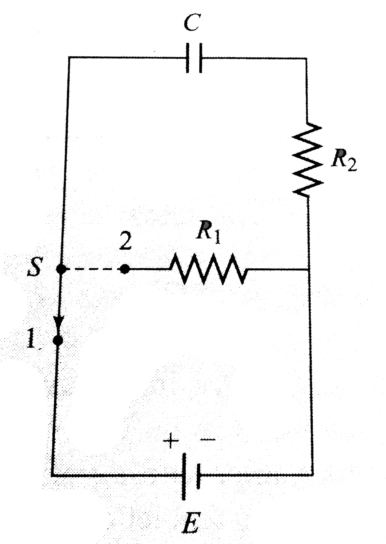
- Switch S of circuit shown in Fig 5.200 is in position 1 for a long tim...
Text Solution
|
- A charged capacitor C1 is discharged through a resistance R by putting...
Text Solution
|
- The capacitor shown in figure has been charged to a potential differen...
Text Solution
|
- A part of a circuit in steady state along with the currents flowing in...
Text Solution
|
- An infinite ladder is constructed with 1(Omega)and 2(Omega)resistor as...
Text Solution
|
- The circuit diagram shwon in the fig consist of a large number of elem...
Text Solution
|
- Each component in the infinite network shwon in fig has a resistance R...
Text Solution
|
- In the circuit shown in fig calculate chare on capacitors C1 and C2 i...
Text Solution
|
- Analyze the circuit, find the charge in capactiors C1 C2, and C3 in st...
Text Solution
|
- Idnetical resistor each of resistance r are connected as shown in figu...
Text Solution
|
- initially the switch is open for a long time. Now the swithc is closed...
Text Solution
|
- If a battery of emf 8V and netgligible internal resistance in connecte...
Text Solution
|