Home
Class 12
PHYSICS
In the circuit of figure. Treat the diod...

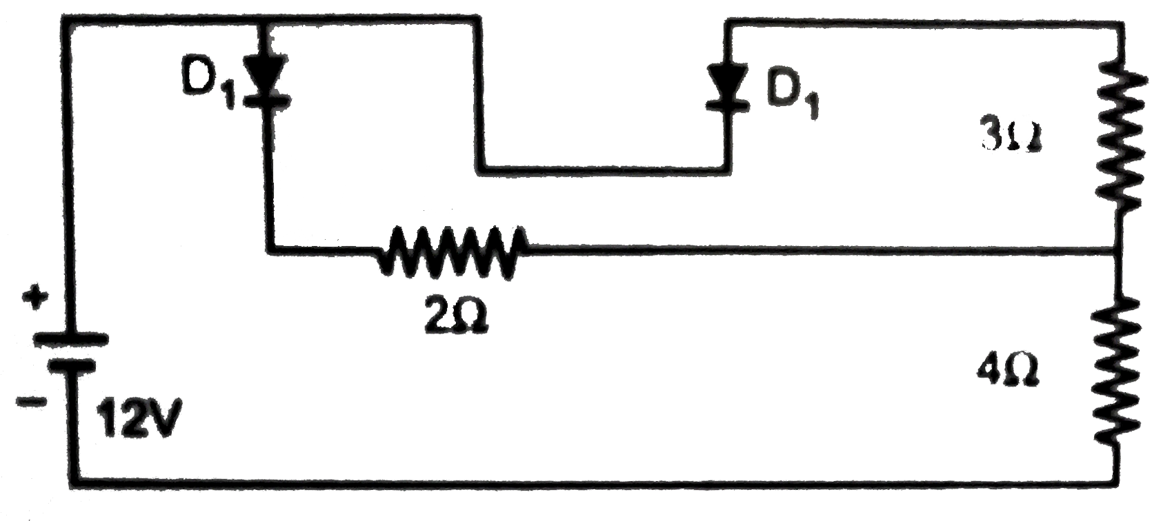
In the circuit of figure. Treat the diodes as ideal. Current in the `4` ohm resistor is

A

`2 A`

B

`3 A`

C

`12//7 A`

D

`30//13 A`

Text Solution

Verified by Experts

The correct Answer is:
A

With battery polarity, `D_(2)` is off. So, `I=12/(4+2)=2A`.
Promotional Banner

Topper's Solved these Questions

  • SEMICONDUCTOR ELECTRONICS

    A2Z|Exercise Section B - Assertion Reasoning|22 Videos
  • SEMICONDUCTOR ELECTRONICS

    A2Z|Exercise AIPMT/NEET Questions|77 Videos
  • SEMICONDUCTOR ELECTRONICS

    A2Z|Exercise Digital Electronics|40 Videos
  • NUCLEAR PHYSICS

    A2Z|Exercise Section D - Chapter End Test|29 Videos
  • SOURCE AND EFFECT OF MAGNETIC FIELD

    A2Z|Exercise Section D - Chapter End Test|30 Videos

Similar Questions

Explore conceptually related problems

In the circuit of the figure, treat diode as ideal, current in the 4 Omega resistor is

In the circuit shown in figure , all the cells are ideal . The current through 2Omega resistor is

Four silicon diodes are connected as shown in the figure. Assuming the diodes to be ideal. The current through the resistor R is

A diode is a device that allows current to be carried in only one direction (the direction indicated by the arrowhead in its circuit symbol). Find (approximately) in terms of DeltaV and R the average power delivered to the diode circuit of the figure. Assume that the diodes are ideal and DeltaV is the rms voltage applied to the circuit.

In the circuit shown below, the current in the resistor is:

In the circuit diagram given below, the current flowing across 5 ohm resistor is 1 amp. Find the current flowing through the other two resistors.

In the circuit shown in fig the heat produced in the 5 ohm resistor due to the current flowing through it is 10 calories per second. The heat generated in the 4 ohms resistor is

In figure , assuming the diodes to be ideal ,

In the diode circuit shown in figure,

In the circuit shown in figure , the diode is ideal The potential difference between A and B is

Knowledge Check

  • A diode is a device that allows current to be carried in only one direction (the direction indicated by the arrowhead in its circuit symbol). Find (approximately) in terms of DeltaV and R the average power delivered to the diode circuit of the figure. Assume that the diodes are ideal and DeltaV is the rms voltage applied to the circuit.

    A
    `((DeltaV)^(2))/(R ) xx 0.6`
    B
    `((DeltaV)^(2))/(R ) xx 0.8`
    C
    `((DeltaV)^(2))/(R ) xx 1.1`
    D
    `((DeltaV)^(2))/(R ) xx 1.4`
  • In the circuit shown in fig the heat produced in the 5 ohm resistor due to the current flowing through it is 10 calories per second. The heat generated in the 4 ohms resistor is

    A
    `1cal//sec`
    B
    `2cal//sec`
    C
    `3cal//sec`
    D
    `4cal//sec`
  • In figure , assuming the diodes to be ideal ,

    A
    (a) ` D_1 ` is forward biased and ` D_2` is reverse biased and hence current flows from A to B.
    B
    ` D_2 ` is forward biased and `D_1` is reverse biased and hence no current flows from B to A and vice - versa.
    C
    `D_1` and `D_2` are both forward biased and hence current flows from A to B.
    D
    `D_1` and `D_2` are both reverse biased and hence no current flows from A to B and vice versa.
  • A2Z-SEMICONDUCTOR ELECTRONICS-Problems Based On Mixed Concepts
    1. In the circuit of figure. Treat the diodes as ideal. Current in the 4 ...

      Text Solution

      |

    2. The potential barrier developed in the diode of figure is 0.5 V. The c...

      Text Solution

      |

    3. Identify the logic gate G in the combination of gates shown in fig. Th...

      Text Solution

      |

    4. The current amplification of the common base NPN transistor is 0.96. W...

      Text Solution

      |

    5. In figure the current supplied by the battery is

      Text Solution

      |

    6. Figure shows a piece of semiconductor (pure one) S in series with a va...

      Text Solution

      |

    7. A semiconductor diode and a resistor of constant resistance are connec...

      Text Solution

      |

    8. A transistor is used in a common-emitter mode in an amplifier circuit....

      Text Solution

      |

    9. A transistor is used in common-emitter mode in an amplifier circuit. W...

      Text Solution

      |

    10. A transistor is used in common-emitter mode in an amplifier circuit. W...

      Text Solution

      |

    11. In a common emitter amplifier, using output reisistance of 5000 ohm an...

      Text Solution

      |

    12. In a common emitter amplifier, using output reisistance of 5000 ohm an...

      Text Solution

      |

    13. A sinusiodal voltage of rms value 200 volt is connected to the diode a...

      Text Solution

      |

    14. In the circuit shown, the base current is 30muA. The value of R(1) is

      Text Solution

      |

    15. The diagram shows a logic network. If the inputs L,M and N are al...

      Text Solution

      |

    16. In the circuit shown in the diagram, the operational amplifier may be ...

      Text Solution

      |

    17. An input voltage V(i) of 0.20 V is applied to an operational amplifier...

      Text Solution

      |

    18. The function of a half -adder may be represented as shown in Figure. ...

      Text Solution

      |

    19. The diagram shows an operational circuit. Which of the following corre...

      Text Solution

      |

    20. A digital system comprises a HAND gate with a NOT gate on each of its ...

      Text Solution

      |