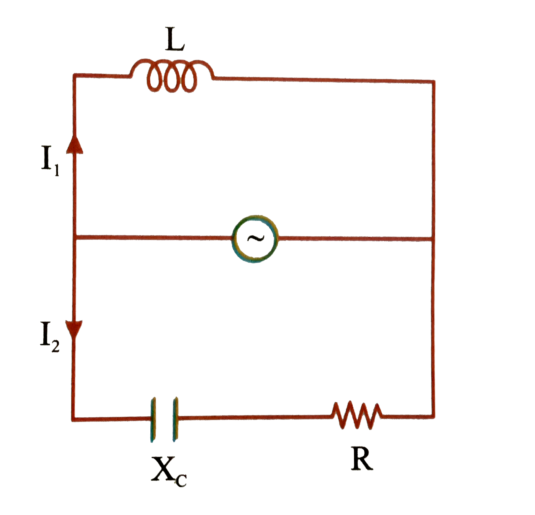
A
B
C
D
Text Solution
Verified by Experts
The correct Answer is:
Topper's Solved these Questions
DAILY PRACTICE PROBLEM
RESONANCE|Exercise DPP No.62|9 VideosDAILY PRACTICE PROBLEM
RESONANCE|Exercise DPP No.63|9 VideosDAILY PRACTICE PROBLEM
RESONANCE|Exercise DPP No.60|9 VideosCURRENT ELECTRICITY
RESONANCE|Exercise High Level Problems (HIP)|21 VideosELECTRO MAGNETIC WAVES
RESONANCE|Exercise Exercise 3|27 Videos
Similar Questions
Explore conceptually related problems
RESONANCE-DAILY PRACTICE PROBLEM-DPP No.61
- In the given circuit assuming inductor and source to be ideal, the pha...
Text Solution
|
- Three identical circular coils A, B and C are placed coaxial (with pla...
Text Solution
|
- Two plane circular coilds P and Q have radii r(1) and r(2), respective...
Text Solution
|
- The time required for a 50Hz alternating current to increase from zero...
Text Solution
|
- The self-inductance of a coil is 2H. The current in the coil changes f...
Text Solution
|
- In the figure given below, the position time graph of a particle of ma...
Text Solution
|
- If at t = 0 the switch S(w) is closed , then the charge on capacitor (...
Text Solution
|
- Let (nr) and (nb) be respectively the number of photons emitted by a r...
Text Solution
|
- The dimensions of shear modulus are
Text Solution
|
- A particle of mass m is given initial horizontal velocity of magnitude...
Text Solution
|
- In the figure shown, a small ball of mass 'm' can move witgout sliding...
Text Solution
|
- A projectile of range R bursts at its highest point in two fragments, ...
Text Solution
|
- Two men of equal masses stand at opposite ends of the diameter of a tu...
Text Solution
|
- Two identical long, solid cylinders are used to conduct heat from temp...
Text Solution
|
- A force F acts tangentially at the highest point of a sphere f mass m ...
Text Solution
|
- A spherical drop of water as 1mm radius. If the surface tension of the...
Text Solution
|
- A sphere of mass m and radius r is projected in a gravity free space w...
Text Solution
|
- A ring of diameter 1m is rotating with an angular momentum of 10 Joule...
Text Solution
|
- A rod of length 1m is sliding in a corner as shown. At an instant when...
Text Solution
|
- A point charge placed on the axis of a uniformly charged disc experien...
Text Solution
|
