In the circuit shown in figure
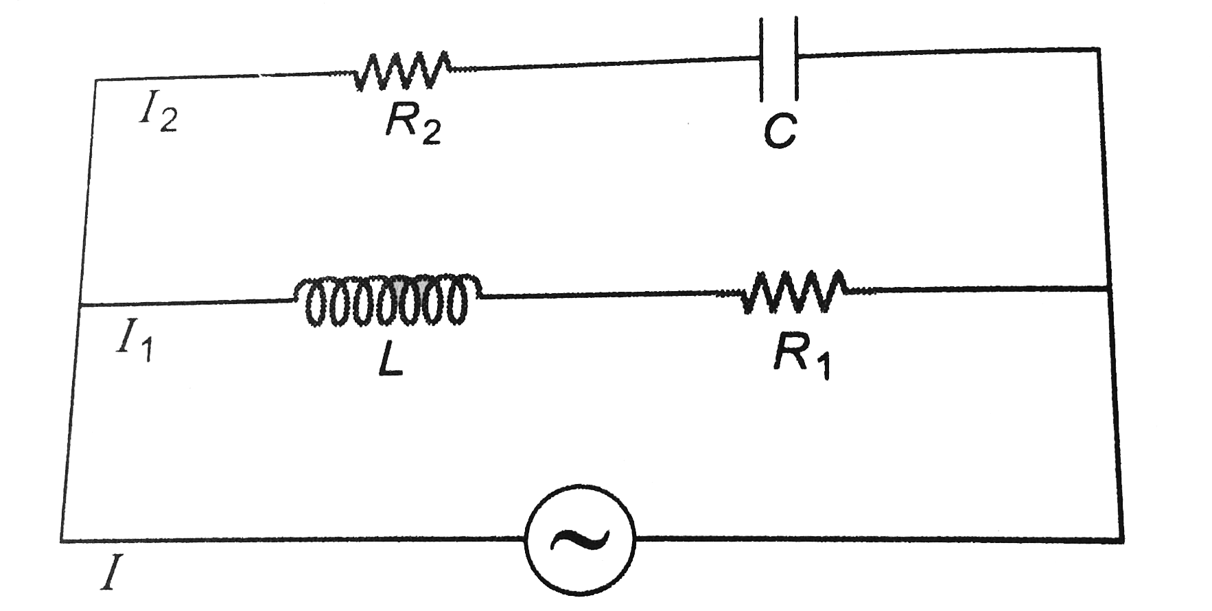
`R_1=30Omega, R_2=40 Omega, L=0.4H` and `C=1/3mF`.
Find seven function of time `I, I_1, I_2, V_(R_1), V_L, V_(R_2)` and `V_C`. Also total power consumed in the circuit. In the given potential function `V` is in volts and omega in `rad//s`.
In the circuit shown in figure
`R_1=30Omega, R_2=40 Omega, L=0.4H` and `C=1/3mF`.
Find seven function of time `I, I_1, I_2, V_(R_1), V_L, V_(R_2)` and `V_C`. Also total power consumed in the circuit. In the given potential function `V` is in volts and omega in `rad//s`.
`R_1=30Omega, R_2=40 Omega, L=0.4H` and `C=1/3mF`.
Find seven function of time `I, I_1, I_2, V_(R_1), V_L, V_(R_2)` and `V_C`. Also total power consumed in the circuit. In the given potential function `V` is in volts and omega in `rad//s`.
Text Solution
Verified by Experts
Circuit 1 (containing `L` and `R_1`)
`I_1: X_L=omegaL=100xx0.4=40Omega`
`R_1=30Omega`
`:. Z_1=sqrt(R_1^2+X_L^2)=sqrt((30)^2+(40)^2)`
`=50Omega` ltbRgt Maximum value of current `I_1=V_0/Z_1=200/50=4A`
Since there is only `X_L` so voltage function will lead the current function by angle `phi_1`, where
`cosphi_1=R_1/Z_1=30/50=3/5`
`:. phi_1=53^@`
`:. I_1=4sin(100t+30^(@)-53^(@))`
or `I_1=4sin(100t-23^@)`
`V_(R_1)-V_(R_1)` function is in phase with `I_1` function
Maximum value of `V_(B_1)`=(maximum value of `I_1`) `(R_1)`
`=(4)(30)`
`=120` volt
`V_(R_1)=120sin(100t-23^@)`
`V_L:V_L` function is `90^@` ahead of `I_1` function.
Maximum value of `V_L=` (maximum value of `I_1`) `(X_L)`
`=(4)(40)=160` volt
`V_L=160sin(100t-23^@+90^@)`
`:. V_L=160sin(100t+67^@)`
power in this circuit power will be consumed only across `R_1`. This power is given by
`P_(R_1)`=(rms value of `I_1)^2R_1`
`(4/sqrt2)^2(30)`
`=240watt`
Circuit 2 (containing `C` and `R_2`)
`I_2: X_C=1/(omega_C)=1/(100xx1/3xx10^-3)=30Omega`
`R_2=40 Omega`
`Z_2=sqrt(R_2^2+X_C^2)`
`=sqrt((40)^2+(30)^2)`
`=50 Omega`
Maximum value of `I_2=V_0/Z_2=200/50=4A`
Since, there is only `X_C,` so `I_2` function will lead the `V` function by an angle `phi_2` where
`cosphi_2=R_2/Z_2=40/50=4/5`
`:. phi_2=37^@`
`V_(R_1):V_(R_2) ` function is in phase with `I_2` function
Maximum value of `V_(R_2)=` (maximum value of `I_2`) `(R_2)`
`=4xx40=160` volt
`V_(R_2)=160sin(100t+67^@)`
`V_C:V_C` function lags `I_2` function of `90^@`
maximum value of `V_C=` (maximum value of `I_2`) `(X_C)`
`=4xx30`
`=120` volt
`V_C=120sin(100t+37^@-90^@)`
or `V_C=120sin(100t-23^@)`
Power in this circuit, power will be consumed only across `R_2` and this power is given by
`R_(R_2)` =(rms value of `I_2)^2R_2`
`=(4/sqrt2)^2(40)`
`=320W`
`:.` Total power consumed in the circuit
`P=P_(R_1)+P_(R_2)`
`(240+320)W`
`=560W`
`I: I=I_1+I_2`
`I=4sin(100t-23^@)+4sin(100t-67^@)`
Now the amplutide can be added by vector method.
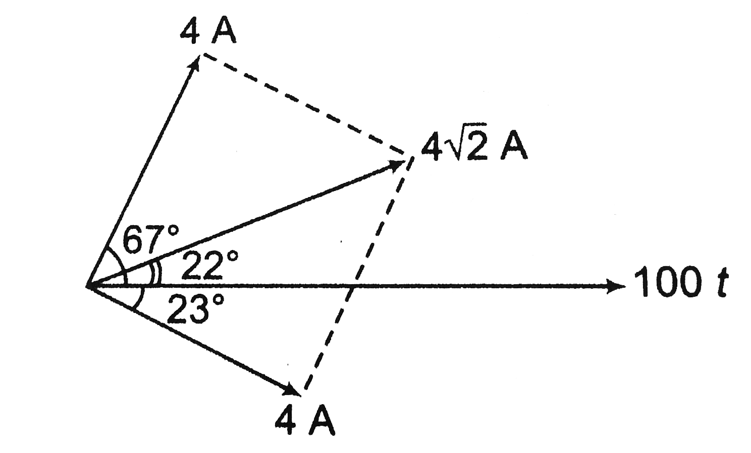
Resultant of `4 A` and `4A` at `90^@` is `4sqrt2` at `45^@` from both currents or at `22^@` from 100 t line
`I=4sqrt2sin(100t+22^@)`.
`I_1: X_L=omegaL=100xx0.4=40Omega`
`R_1=30Omega`
`:. Z_1=sqrt(R_1^2+X_L^2)=sqrt((30)^2+(40)^2)`
`=50Omega` ltbRgt Maximum value of current `I_1=V_0/Z_1=200/50=4A`
Since there is only `X_L` so voltage function will lead the current function by angle `phi_1`, where
`cosphi_1=R_1/Z_1=30/50=3/5`
`:. phi_1=53^@`
`:. I_1=4sin(100t+30^(@)-53^(@))`
or `I_1=4sin(100t-23^@)`
`V_(R_1)-V_(R_1)` function is in phase with `I_1` function
Maximum value of `V_(B_1)`=(maximum value of `I_1`) `(R_1)`
`=(4)(30)`
`=120` volt
`V_(R_1)=120sin(100t-23^@)`
`V_L:V_L` function is `90^@` ahead of `I_1` function.
Maximum value of `V_L=` (maximum value of `I_1`) `(X_L)`
`=(4)(40)=160` volt
`V_L=160sin(100t-23^@+90^@)`
`:. V_L=160sin(100t+67^@)`
power in this circuit power will be consumed only across `R_1`. This power is given by
`P_(R_1)`=(rms value of `I_1)^2R_1`
`(4/sqrt2)^2(30)`
`=240watt`
Circuit 2 (containing `C` and `R_2`)
`I_2: X_C=1/(omega_C)=1/(100xx1/3xx10^-3)=30Omega`
`R_2=40 Omega`
`Z_2=sqrt(R_2^2+X_C^2)`
`=sqrt((40)^2+(30)^2)`
`=50 Omega`
Maximum value of `I_2=V_0/Z_2=200/50=4A`
Since, there is only `X_C,` so `I_2` function will lead the `V` function by an angle `phi_2` where
`cosphi_2=R_2/Z_2=40/50=4/5`
`:. phi_2=37^@`
`V_(R_1):V_(R_2) ` function is in phase with `I_2` function
Maximum value of `V_(R_2)=` (maximum value of `I_2`) `(R_2)`
`=4xx40=160` volt
`V_(R_2)=160sin(100t+67^@)`
`V_C:V_C` function lags `I_2` function of `90^@`
maximum value of `V_C=` (maximum value of `I_2`) `(X_C)`
`=4xx30`
`=120` volt
`V_C=120sin(100t+37^@-90^@)`
or `V_C=120sin(100t-23^@)`
Power in this circuit, power will be consumed only across `R_2` and this power is given by
`R_(R_2)` =(rms value of `I_2)^2R_2`
`=(4/sqrt2)^2(40)`
`=320W`
`:.` Total power consumed in the circuit
`P=P_(R_1)+P_(R_2)`
`(240+320)W`
`=560W`
`I: I=I_1+I_2`
`I=4sin(100t-23^@)+4sin(100t-67^@)`
Now the amplutide can be added by vector method.
Resultant of `4 A` and `4A` at `90^@` is `4sqrt2` at `45^@` from both currents or at `22^@` from 100 t line
`I=4sqrt2sin(100t+22^@)`.


Topper's Solved these Questions
Similar Questions
Explore conceptually related problems
In the diagram shown in figure, V function is given. Find other four functions of time I, V_C, V_R and V_L . Also, find power consumed in the circuit, V is given in volts and omega in rad/s.
In the circuit shown in figure E_1=10 V, E_2=4V, r_1=r_2=1Omega and R=2Omega . Find the potential difference across battery 1 and battery 2.
In the circuit shown in figure E_1=7V,E_2=1 V,R_1=2Omega, R_2=2Omega and R_3=3Omega respectively. Find the power supplied by the two batteries.
In the given figure, E=12V, R_(1)=3Omega, R_(2)=2Omega" and "r=1Omega . The choose the correct option/s
In the circuit diagram shown in Figure E=18V , L=2H, R_(1)=3Omega , R_(2)=6Omega . Switch S is closed at t=0 Match the following:
In the circuit shown in adjoining fig E =10V, R_(1)=1 Omega R_(2)=2 Omega, R_(3)=3 Omega and L=2H . Calculate the value of current i_(1), i_(2) and i_(3) immidiately after key S is closed :-
In the circuit given in fig. (V_C)=50 V and R=50 Omega . The values of C and (V_R) are
In the circuit shown in figure. epsi_(1)=3,epsi_(2)=2,epsi_(3)=6V,R_(1)=2,R_(4)=6Omega,R_(3)=2,R_(2)=4Omega and C=5muF . Find the current in the resistor R_(3) and the electrical energy stored in the capacitor C.
In the circuit shown below E_(1) = 4.0 V, R_(1) = 2 Omega, E_(2) = 6.0 V, R_(2) = 4 Omega and R_(3) = 2 Omega . The current I_(1) is
In the following circuit , E_1 = 4V, R_1 = 2 Omega, E_2 = 6 V, R_2 = 2Oemga, and R_3 = 4Omega. Find the currents i_1 and i_2