Home
Class 12
PHYSICS
A 100 W bulb B1, and two 60 W bulb B2 an...

A 100 W bulb `B_1`, and two 60 W bulb `B_2` and `B_3`, are connected to a 250 V source, as shown in figure. Now `W_1, W_2 and W_3` are the output powers of the bulbs `B_1, B_2 and B_3`, respectively. Then

A

`W_1gtW_2 = W_3`

B

`W_1gtW_2gtW_3`

C

`W_1ltW_2 = W_3`

D

`W_1ltW_2ltW_3`

Text Solution

Verified by Experts

The correct Answer is:
D

(d) KEY CONCEPT : `R = V^2/P`
`:. R_1 = V^2/100 , R_2 = V^2/60 = R_3,`

`W_1 = (V_(1)^2)/(R_1) = (v^2R_1)/(R_1 + R_2)^2 , W_2 = (V_(2)^2)/R^2 = (V^2R_2)/(R_1 + R_2)^2` .
and `W_3 = V^2/R_3`
`W_3 : W_2: W_1 = (250)^2/R_3 : ((250)^2R_2)/(R_1+R_2)^2 R_2 : (250)^2 / (R_1 + R_2)^2 R_1`
or `W_3 : W_2 : W_1. `
`=(250)^2/V^2 xx 60 : (250)^2/([1/100 + 1/60]^2 V^4) xx v^2/60 : ((250)^2V^2)/([1/100 + 1/60]^2 V^4 xx 100)`
or `W_3 : W_2 : W_1,`
`= 60 : (100 xx 100 xx 60 xx 60)/(160 xx 160 xx 60) : (100 xx 100 xx 60 xx 60)/(160 xx 160 xx 100)`
`=64:25:15` .
Promotional Banner

Topper's Solved these Questions

  • ELECTROMAGNETIC INDUCTION AND ALTERNATING CURRENT

    SUNIL BATRA (41 YEARS IITJEE PHYSICS)|Exercise JEE Main And Advanced|107 Videos

Similar Questions

Explore conceptually related problems

A 100 W bulb B_1 , and two 60 W bulbs B_2 and B_3 are connected to a 250 V source as shown in the figure. Now W_1,W_2 and W_3 are the output powers of the bulbs B_1, B_2 and B_3 respectively. Then

A 100 W bulb B_(1) and two 60 W bulbs B_(2) and B_(3) , are connected to a 250V source, as shown in the figure now W_(1),W_(2) and W_(3) are the output powers of the bulbs B_(1),B_(2) and B_(3) respectively then

Three bulbs of 40 W , 60 W and 100 W are connected in series with a 240 V source.

When two electric bulbs of 40W and 60W are connected in parallel, then the:

Bulb B_1(100W - 250W) and bulb B_2(100W - 200V) are connected across 250V. What is potential drop across B_2 ?

A 25 W , 220 V bulb and a 100 W , 220 V bulb are connected in parallel across a 440 V line

Two bulbs 100 W, 250 V and 200 W, 250 V are connected in parallel across a 500 V line. Then-

Three electric bulbs of 200 W, 200 W and 400 W are connected as shown in figure. The resultant power of the combination is

Three 60 W , 120 V light bulbs are connected across a 120 V power lines as shown in Fig. 7.26 . Find (a) the voltage across each bulb and (b) the total power dissipated in the three bulbs.

SUNIL BATRA (41 YEARS IITJEE PHYSICS)-CURRENT ELECTRICITY-JEE Main And Advanced
  1. In the given circuit, it is observed that the current I is independent...

    Text Solution

    |

  2. The effective resistance between points P and Q of the electrical ci...

    Text Solution

    |

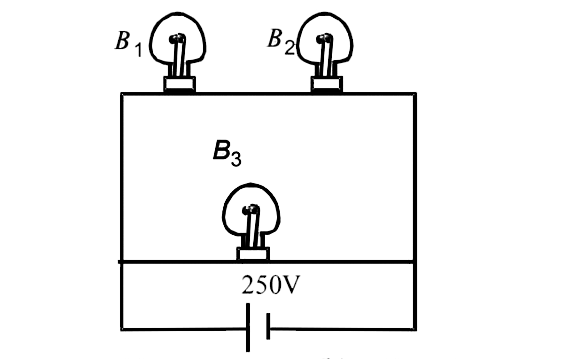
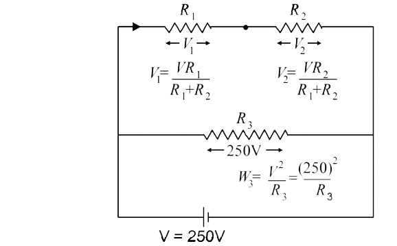
  3. A 100 W bulb B1, and two 60 W bulb B2 and B3, are connected to a 250 V...

    Text Solution

    |

  4. Express which of the following set ups can be used to verify ohm's l...

    Text Solution

    |

  5. In the shown arrangement of the experiment of the meter bridge if AC c...

    Text Solution

    |

  6. The three resistance of equal value are arranged in the different comb...

    Text Solution

    |

  7. Shown in figure is a Post Office box. In order to calculate the value ...

    Text Solution

    |

  8. Six identical resistors are connected as shown in the figure. The equi...

    Text Solution

    |

  9. A capacitor is charged using an external battery with a resistance x i...

    Text Solution

    |

  10. Find out the value of current through 2Omega resistance for the given ...

    Text Solution

    |

  11. A 4 muF capacitor, a resistance of 2.5 M Omega is in series with 12V b...

    Text Solution

    |

  12. A moving coil galvanometer of resistance 100Omega is used as an ammete...

    Text Solution

    |

  13. An ideal gas is filled in a closed rigid and thermally insulated conta...

    Text Solution

    |

  14. If a steady current I is flowing through a cylindrical element ABC. Ch...

    Text Solution

    |

  15. A resistance of 2Omega is connected across one gap of a metre-bridge(t...

    Text Solution

    |

  16. A circuit is connected as shown in the figure with the switch S open. ...

    Text Solution

    |

  17. Figure shows three resistor configurations R1,R2 and R3 connected to 3...

    Text Solution

    |

  18. Incandescent bulbs are designed by keeping in mind that the resistance...

    Text Solution

    |

  19. To verify Ohm's law, a student is provided with a test resistor RT, a ...

    Text Solution

    |

  20. Consider a thin square sheet of side L and thickness t, made of a mate...

    Text Solution

    |