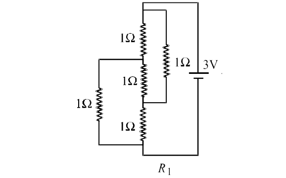
Home
Class 12
PHYSICS
Figure shows three resistor configuratio...

Figure shows three resistor configurations `R_1,R_2 and R_3` connected to 3V battery. If the power dissipated by the configuration `R_1,R_2 and R_3` is `P_1, P_2 and P_3`, respectively. Then -
, ,

A

`P_1gtP_2gtP_3`

B

`P_1gtP_3gtP_2`

C

`P_2gtP_1gtP_3`

D

`P_3gtP_2gtP_1`

Text Solution

Verified by Experts

The correct Answer is:
C

(c) We Know that `P = V^2/R`
For constant value of potential difference (V) we have
` P prop 1/R`
Case (i)

This is a case of balanced Wheatstone bridge `R_1 = 1Omega`
Case (ii)
Clearly the equivalent resistance `(R_2)` will be less than
`1Omega.`
Case (iii)
Thus, `R_3 = 2Omega`
Since, `R_2 lt R_1 lt R_3`
`:. P_2gt P_1gt P_3`.
Promotional Banner

Topper's Solved these Questions

  • ELECTROMAGNETIC INDUCTION AND ALTERNATING CURRENT

    SUNIL BATRA (41 YEARS IITJEE PHYSICS)|Exercise JEE Main And Advanced|107 Videos

Similar Questions

Explore conceptually related problems

Figure shows three resistor configurations R1,R2 and R3 connected to 3 V battery . If the powers dissipated by the configuration R1,R2 and R3 are P1,P2 and P3, respectively, then

Figure shows three resistor configurations R1,R2 and R3 connected to 3V vattery If the prower dissipated by the configuration R1,R2 and R3 is P1 ,m P2 and P3 repecitively then Figure

Figure shows three resistor configurations R_(1),R_(2) and R_(3) connected to 3V battery. If the power dissipated by the configurations R_(1),R_(2) and R_(3) is P_(1),P_(2) and P_(3) respectively, then

A resistor of resistance R is connected to an ideal battery. If the value of R is decreased,the power dissipated in the resistor will

Three identical resistors R_(1) = R_(2) = R_(3) are connected as shown to a battery of constant e.m.f . The power dissipated is

Three resistors having values R_1,R_2 and R_3 are connected in series to a battery.Suppose R_1 carries a current of 2.0 A, R_2 has resistance of 3.0 ohms, and R_3 dissipates. 6.0 watts of power. Then the voltage across R_3 is

SUNIL BATRA (41 YEARS IITJEE PHYSICS)-CURRENT ELECTRICITY-JEE Main And Advanced
  1. A resistance of 2Omega is connected across one gap of a metre-bridge(t...

    Text Solution

    |

  2. A circuit is connected as shown in the figure with the switch S open. ...

    Text Solution

    |

  3. Figure shows three resistor configurations R1,R2 and R3 connected to 3...

    Text Solution

    |

  4. Incandescent bulbs are designed by keeping in mind that the resistance...

    Text Solution

    |

  5. To verify Ohm's law, a student is provided with a test resistor RT, a ...

    Text Solution

    |

  6. Consider a thin square sheet of side L and thickness t, made of a mate...

    Text Solution

    |

  7. A meter bridge is set up as shown, to determine an unknown resistance ...

    Text Solution

    |

  8. During an experiment with a metre bridge, the galvanometer shows a nul...

    Text Solution

    |

  9. An infinite line charge of uniform electric charge density lambda lies...

    Text Solution

    |

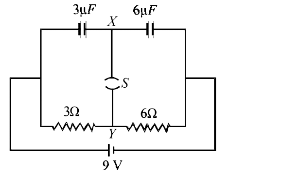
  10. Capacitor C1 of capacitance 1 micro-farad and capacitor C2 of capacita...

    Text Solution

    |

  11. Read the following statements carefully : Y : The resistivity of a s...

    Text Solution

    |

  12. In the circuit shown in figure the current through

    Text Solution

    |

  13. When a potential difference is applied across, the current passing thr...

    Text Solution

    |

  14. For the circuit shown in figure

    Text Solution

    |

  15. For the resistance network shown in the figure, choose the correct opt...

    Text Solution

    |

  16. Heater of an electric kettle is made of a wire of length L and diamete...

    Text Solution

    |

  17. Two ideal batteries of emf V1 and V2 and three resistances R1, R2 and ...

    Text Solution

    |

  18. In an aluminium (Al) bar of square cross section, a square hole is dri...

    Text Solution

    |

  19. An incandescent bulb has a thin filament of tungsten that is heated to...

    Text Solution

    |

  20. In the circuit shown below, the key is pressed at time t = 0 . Which o...

    Text Solution

    |