Home
Class 12
PHYSICS
Two ideal batteries of emf V1 and V2 and...

Two ideal batteries of emf `V_1 and V_2` and three resistances `R_1, R_2 and R_3` are connected as shown in the figure. The current in resistance `R_2` would be zero if

A

`V_1 = V_2 and R_1 = R_2 = R_3`

B

`V_1 = V_2 and R_1 = 2R_2 = R_3`

C

`V_1 = 2V_2 and 2R_1= 2R_2 = R_3`

D

`2V_1 = V_2 and 3R_1 = R_2 = R_3`

Text Solution

Verified by Experts

The correct Answer is:
A, B, D

(a,b,d) Applying KVL in MNOPQAM
`V_1 -iR_1 + V_2 -iR_3 = 0`
`:. i = (V_1+V_2)/(R_1+R_3)` ……..(i)
Applying KVL in NOPQN
`V_1 - iR_1 = 0 :. I = V/R_1` ……(ii)
From (i) & (ii) `V_1/R_1 = (V_1+ V_2)/(R_1 + R_3)`
`:. V_1R_1 + V_1R_3 = V_1R_1 + V_2R_1`
`rArr V_1R_3 = V_2R_1`
If `V_1 = V_2 then R_1 = R_3 = R_2 :. ` (a) is correct option.
If `V_1 = V_2 then R_1 = R_3 = 2R_2 :. ` (b) is correct option.
`(R_2 can have any value as there is no current flowing
through d)
If `V_1 = 2V_2 the 2R_3 = R_1 :.` (c) is incorrect option.
If `2V_1 = V_2 then R_3 = 2R_1 = R_2 :.` (d) is correct option.
Promotional Banner

Topper's Solved these Questions

  • ELECTROMAGNETIC INDUCTION AND ALTERNATING CURRENT

    SUNIL BATRA (41 YEARS IITJEE PHYSICS)|Exercise JEE Main And Advanced|107 Videos

Similar Questions

Explore conceptually related problems

Two ideal batteries of emf V_(1)andV_(2) and these resistances R_(1),R_(2)andR_(3) are connected as shown in the figure . The current in resistance R_(2) would be zero if

Two ideal batteries of emf V_(1) and V_(2) and three resistance R_(1)R_(2) and R_(3) are connected The current in resistance R_(2) would be zero if

Two batteries of emf E_(1) and E_(2)(E_(2) gt E_(1)) and internal resistance r_(1) and r_(2) respectively are connected in parallel as shown in the figure. Then, which of the followings statements is correct ?

Two non-ideal batteries have e.m.f 2V and 8V respectively and internal resistance 1 Omega and 2 Omega respectively as shown in the figure. If the potential difference between a and b is zero then the resistance R has a value

Three resistors having resistance r_1 , r_2 , r_3 are connected as shown. The ratio i_3/i_1 of current in terms of resistance used in circuit is

Two indentical batteries, each of emf 2V andinternal resistance r=1Omega are connected as shown. The maximum power that can be developed across R using these batteries is

SUNIL BATRA (41 YEARS IITJEE PHYSICS)-CURRENT ELECTRICITY-JEE Main And Advanced
  1. For the resistance network shown in the figure, choose the correct opt...

    Text Solution

    |

  2. Heater of an electric kettle is made of a wire of length L and diamete...

    Text Solution

    |

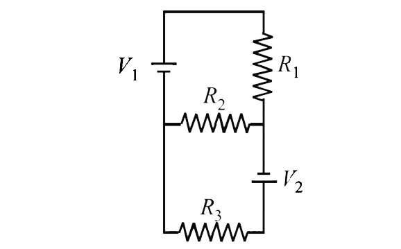
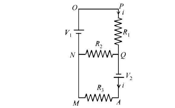
  3. Two ideal batteries of emf V1 and V2 and three resistances R1, R2 and ...

    Text Solution

    |

  4. In an aluminium (Al) bar of square cross section, a square hole is dri...

    Text Solution

    |

  5. An incandescent bulb has a thin filament of tungsten that is heated to...

    Text Solution

    |

  6. In the circuit shown below, the key is pressed at time t = 0 . Which o...

    Text Solution

    |

  7. A heater is designed to operate with a power of 1000 walts in a 100 vo...

    Text Solution

    |

  8. If a copper wire is stretched to make it 0.1% longer wha is the percen...

    Text Solution

    |

  9. Find the equivalent resistance of the network shown in figure between ...

    Text Solution

    |

  10. In the diagram shown find the potential difference between the points ...

    Text Solution

    |

  11. A battery of emf 2 volts and internal resistance 0.1 ohm is being char...

    Text Solution

    |

  12. State ohm's law. In the circuit shown in figure, a voltmeter reads 3...

    Text Solution

    |

  13. In the circuit shown in fig E1 = 3 volts, E2 = 2volts, E3 = 1volt and ...

    Text Solution

    |

  14. Calculate the steady state current in the 2- ohm resistor shown in the...

    Text Solution

    |

  15. In the circuit shown in figure E,F, G and H are cell of emf 2,1,3, and...

    Text Solution

    |

  16. A part of circuit in a steady state along with the currents flowing in...

    Text Solution

    |

  17. An infinite ladder is constructed with 1(Omega)and 2(Omega)resistor as...

    Text Solution

    |

  18. In the given circuit E1 = 3E2 = 2E3 = 6 volts R1 = 2R4 = 6ohms R3...

    Text Solution

    |

  19. An elctrical circuit is shown in Fig. Calculate the potential differen...

    Text Solution

    |

  20. In the circuit shown in Figure, the battery is an ideal one, with emf ...

    Text Solution

    |