Home
Class 12
PHYSICS
In the circuit shown in fig E1 = 3 volts...

In the circuit shown in fig `E_1 = 3 volts, E_2 = 2volts, E_3 = 1volt and R = r_1 = r_2= r_3= 1 ohm.`

(i) Find the potential difference between the points A and B and the currents through each branch.
(ii) If `r_2` is short circuited and the point A is connected to point B, find the current through `E_1, E_2, E_3` and the resistor R.

Text Solution

Verified by Experts

The correct Answer is:
A, B

(i) `V_(AB) = (SigmaE//r)/(Sigma 1/r) = (E_1/r_1 + E_2/r_2 + E_3/r_3)/(1/r_1 + 1/r_2 + 1/r_3)`
(ii)
Applying Kirchoff's law in PQRUP starting from P moving
clockwise
`I_1r_1 - E_1 + E_2 = 0 or I_1-3+2 = 0`
or `I_1 = 1 amp`
Applying Kirchoff's law in URSTU starting from U moving
clockwise
`-E_2 + E_3 - I_3r_3 = 0 `
or `-2 + 1-I_3 = 0`
or `I_3 = -1 amp`
`(I_1+I_2+ I_3) R -E_2 = 0 or (1+ I_2-1) R=2`
or `I_2 = 2amp`
Current through `R is I_1+ I_2 + I_3 = 2A`.
Promotional Banner

Topper's Solved these Questions

  • ELECTROMAGNETIC INDUCTION AND ALTERNATING CURRENT

    SUNIL BATRA (41 YEARS IITJEE PHYSICS)|Exercise JEE Main And Advanced|107 Videos

Similar Questions

Explore conceptually related problems

In the circuit in figure E_1=3V, E_2=2V, E_3=1V and R=r_1-r_2-r_3=1Omega a. Find the potential differece between the points A and B and the currents through each branch. b. If r_2 is short circuited and the point A is connected to point B , find the currents through E_1,E_2, E_3 and the resistor R

In the circuit shown in fig. E_(1)=3" volt",E_(2)=2" volt",E_(3)=1" vole and "R=r_(1)=r_(2)=r_(3)=1 ohm. (i) Find potential difference in Volt between the points A and B with A & B unconnected. (ii) If r_(2) is short circuited and the point A is coneted to point B through a zero resistance wire, find the current through R in ampere.

In the circuit shown in figure , (epsilon)_(1)=3V,(epsilon)_(2)=2V,(epsilon)_(3)=1V and r_(1)=r_(2)=r_(3)=1(Omega) .Find the potential difference between the points A and B and the current through each branch.

In the circuit as shown in figure, E_(1)=2V , E_(2)=2V, E_(3)=1V, and R=r_(1)=r_(2)=r_(3)Omega . The potential difference between points A and B will be

In the circuit shown in figure E_1=10 V, E_2=4V, r_1=r_2=1Omega and R=2Omega . Find the potential difference across battery 1 and battery 2.

In the circuit shown in fig. 5.265, E_1 = E_2 = E_3 = 2V and R_1 = R_2 = 4Omega. The current flowing between points A and B through battery E_2 is

In the given circuit E_1 = 3E_2 = 2E_3 = 6 volts R_1 = 2R_4 = 6ohms R_3 = 2R_2 = 4ohms C = 5 muf. Find the current in R and the energy stored in the capacitor.

For the circuit shown, with R_1=1.0 Omega,R_2=2.0Omega,E_1=2V and E_2=E_3=4V the potential difference between the points ‘a’ and ‘b’ is __________(in V)

SUNIL BATRA (41 YEARS IITJEE PHYSICS)-CURRENT ELECTRICITY-JEE Main And Advanced
  1. A battery of emf 2 volts and internal resistance 0.1 ohm is being char...

    Text Solution

    |

  2. State ohm's law. In the circuit shown in figure, a voltmeter reads 3...

    Text Solution

    |

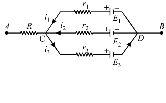
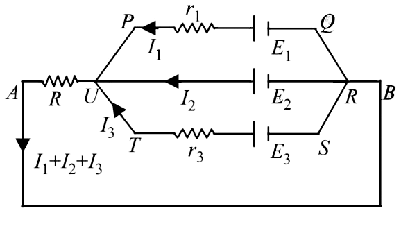
  3. In the circuit shown in fig E1 = 3 volts, E2 = 2volts, E3 = 1volt and ...

    Text Solution

    |

  4. Calculate the steady state current in the 2- ohm resistor shown in the...

    Text Solution

    |

  5. In the circuit shown in figure E,F, G and H are cell of emf 2,1,3, and...

    Text Solution

    |

  6. A part of circuit in a steady state along with the currents flowing in...

    Text Solution

    |

  7. An infinite ladder is constructed with 1(Omega)and 2(Omega)resistor as...

    Text Solution

    |

  8. In the given circuit E1 = 3E2 = 2E3 = 6 volts R1 = 2R4 = 6ohms R3...

    Text Solution

    |

  9. An elctrical circuit is shown in Fig. Calculate the potential differen...

    Text Solution

    |

  10. In the circuit shown in Figure, the battery is an ideal one, with emf ...

    Text Solution

    |

  11. A thin uniform wire Ab of length 1m, an unknown resistance X and a res...

    Text Solution

    |

  12. How a battery is to be connected so that the shown rheostat will behav...

    Text Solution

    |

  13. Draw the circuit diagram to verify Ohm's Law with the help of a main r...

    Text Solution

    |

  14. An unknown resistance X is to be determined using resistances R1, R2 o...

    Text Solution

    |

  15. In the given circuit, the switch S is closed at time t = 0 . The charg...

    Text Solution

    |

  16. Electrical resistance of certain materials, known as superconductors, ...

    Text Solution

    |

  17. Electrical resistance of certain materials, known as superconductors, ...

    Text Solution

    |

  18. Statement-1 : In a Meter Bridge experiment, null point for an unknown ...

    Text Solution

    |

  19. When two identical batteries of internal resistance 1Omega each are co...

    Text Solution

    |

  20. At time t=0, a battery of 10 V is connected across points A and B in t...

    Text Solution

    |