Home
Class 12
PHYSICS
An inductor of inductance L=400 mH and r...

An inductor of inductance L=400 mH and resistor of resistance `R_(1) = 2(Omega) and R_(2) = 2 (Omega)` are connected to a battery of emf E = 12 Vas shown in the figure. The internal resistance of the battery is negligible. The switch S is closed at time t =0. What is the potential drop across L as a function of time? After the steady state is reached, the switch is opened. What is the direction and the magnitude of current through `R_(1)` as a function of time?

Text Solution

Verified by Experts

The correct Answer is:
A, B, C

This is a question on growth and rise of current.
Growth of current: Let at any instant of time t the current be as shown in the figure.
Applying Kirochoff's law in the loop ABCDFGA
we get, starting from G moving clockwise
`E-L(dl_(2))/(dt)-(I_2)(R_2)=0`
or `(I_2)=(E)/(R^2)[1-e^(-(R/L)t)]`

Also, we know that the emf (V) produced across hte inductor
`V=-(d phi)/(dt)=-(d)/(dt)[LI_(2)]=-L(dI_(2))/(dt)`
=-L(d)/(dt)[(E)/(R_2)( 1-e^((-R_(2))/(L)t)]`
`V=-E^((R_2)/(-L)t)`. Here the negative sign shows the opposite to the growth of current.
`:. V+12e(2)/(400xx10^(-3))t=12 e^(-5t)volt`.
DECAY OF CURRENT:When the switch is opened, the branch AG is out of hte circuit CBFDC(in clockwise direction).
Applying Kirchhoff's law
`I(R_(1)+R_(2))-(-(LdI)/(dt)=0`
`:. (dI)/(I)=-(R_(1)+R_(2))/(L) int_(0)^(t) dt`
`:. I=(I_0)e^(-(R_(1)+R_(2)t)/(L)`
here, (R_(1)+R_(2))/(L)=(2+2)/(400xx10^(-3))=10`
and `(I_0)=(E)/(R_(1)+R_(2))=12/4=3A`
`:. I=3e^(-10t)A, clockwise
Alternatively, you may directly find the time constant
`(tau)=(l)/(R_(1)+R_(2))` and use the equation `i=(i_0)e^(-t//tau)` where `(I-0)=6A`.
Promotional Banner

Topper's Solved these Questions

  • CURRENT ELECTRICITY

    SUNIL BATRA (41 YEARS IITJEE PHYSICS)|Exercise JEE Main And Advanced|129 Videos
  • ELECTROSTATICS

    SUNIL BATRA (41 YEARS IITJEE PHYSICS)|Exercise Comprehension Based Questions|2 Videos

Similar Questions

Explore conceptually related problems

An inductor of inductance L=400 mH and resistors of resistances R_1=2Omega and R_2=2Omega are connected to a battery of emf E=12 V as shown in the figure. The internal resistance of the battery is negligible. The switch S is closed at time t=0 . What is the potential dro across L s a function of time? After the steady state is reached, the switch is opened. What is the direction ad the magnitude of current throough R_1 as a function of time?

An inductor of inductance L = 400 mH and resistors of resistance R_(1) = 2Omega and R_(2) = 2Omega are connected to a battery of emf 12 V as shown in the figure. The internal resistance of the battery is negligible. The switch S is closed at t = 0 . The potential drop across L as a function of time is

An inductor of inductance L=400mH and resistors of resistances R_(1)=2 Omega and R_(2)=2 Omega are connected to a battery of emf 12 V as shown in figure.The internal resistance of the battery is negligible.The switch S is closed at t=0 .The potential drop across L as a function of time is:

An inductor of self-inductance L and resistor of resistance R are connected in series to a battery of emf E and negligible resistance.Calculate the maximum rate at which energy is stored in the inductor.

A 4mu F capacitor is connected to a battery of emf 24V. Through a resistance of 5 M Omega and a switch which is kept open initially. Internal resistance of the battery is negligible. Switch is closed at t=0. Potential difference across capacitor and resistor at t=0 are respectively.

Three capacitors (of capacitances C , 2C and 3C ) and three resistors (of resistance R , 2R and 3R ) are connected with a battery and switch S as shown in the figure. When switch S is open, charges on the capacitors are shown. Switch S is closed at t=0 sec . The time constant of the circuit will be

SUNIL BATRA (41 YEARS IITJEE PHYSICS)-ELECTROMAGNETIC INDUCTION AND ALTERNATING CURRENT-JEE Main And Advanced
  1. A pair of parallel horizontal conducting rails of negligible resistanc...

    Text Solution

    |

  2. A magnetic field B = B(0) (y/a)hatk is into the paper in the +z direct...

    Text Solution

    |

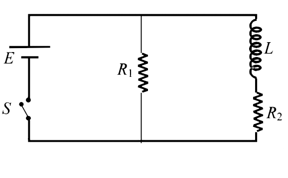
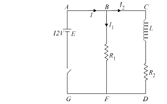
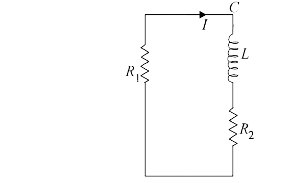
  3. An inductor of inductance L=400 mH and resistor of resistance R(1) = 2...

    Text Solution

    |

  4. A rectangular loop PQRS made from a uniform wire has length a, width b...

    Text Solution

    |

  5. A metal bar AB can slide on two parallel thick metallic rails separate...

    Text Solution

    |

  6. A square loop of side 'a' with a capacitor of capacitance C is located...

    Text Solution

    |

  7. In a series L-R circuit (L=35 mH and R=11 Omega), a variable emf sourc...

    Text Solution

    |

  8. In the figure both cells A and B are of equal emf. Find R for which po...

    Text Solution

    |

  9. A long solenoid of radius a and number of turns per unit length n is e...

    Text Solution

    |

  10. In the given circuit the capacitor (C) may be charged through resistan...

    Text Solution

    |

  11. In the given circuit the capacitor (C) may be charged through resistan...

    Text Solution

    |

  12. In the given circuit the capacitor (C) may be charged through resistan...

    Text Solution

    |

  13. A thermal power plant produed electric power of 600kW at 4000V, which ...

    Text Solution

    |

  14. A thermal power plant produed electric power of 600kW at 4000V, which ...

    Text Solution

    |

  15. A point charges Q is moving in a circular orbit of radius R in the x-y...

    Text Solution

    |

  16. A point charges Q is moving in a circular orbit of radius R in the x-y...

    Text Solution

    |

  17. Statement-1: A vertical iron rod has ciol of wire wound over it at the...

    Text Solution

    |

  18. A series R-C combination is connected to an AC voltage of angular freq...

    Text Solution

    |

  19. A circular wire loop of radius R is placed in the x-y plane centered a...

    Text Solution

    |

  20. Two inductors L(1)(inductors 1 mH, internal resistance 3 Omega) and L(...

    Text Solution

    |