Home
Class 12
PHYSICS
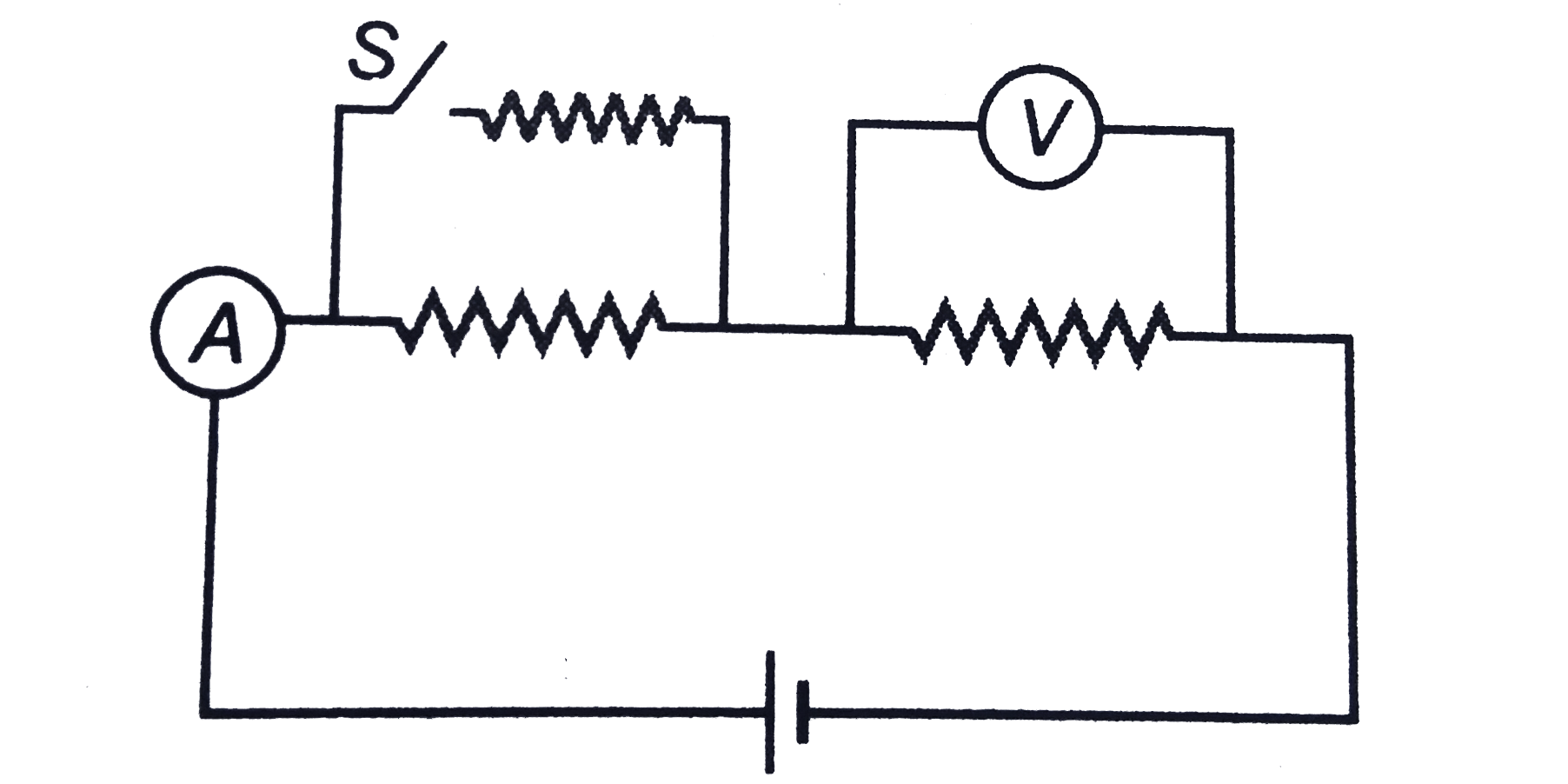
Assertion: In the circuit shown in figur...


Assertion: In the circuit shown in figure after closing the switch `S` reading of ammeter will increase while that of voltmeter will decrease.
Reason : Net resistance decreases as parallel combination of resistors is increased,

A

If both Assertion and Reason are true and the Reason is correct explanation of the Assertion.

B

If both Assertion and Reason are true but Reason is not the correct explanation of Assertion.

C

If Assertion is true, but the Reason is false.

D

If Assertion is false but the Reason is true.

Text Solution

Verified by Experts

The correct Answer is:
D

Since net resistance decreases, therefore main current increases Hence, net potential difference across voltmeter also increases.
Doubtnut Promotions Banner Mobile Dark
|

Topper's Solved these Questions

  • CURRENT ELECTRICITY

    DC PANDEY|Exercise Level 1 Objective|40 Videos
  • CURRENT ELECTRICITY

    DC PANDEY|Exercise OBJECTIVE_TYPE|1 Videos
  • CURRENT ELECTRICITY

    DC PANDEY|Exercise Exercise 23.13|2 Videos
  • COMMUNICATION SYSTEM

    DC PANDEY|Exercise Subjective|11 Videos
  • ELECTROMAGNETIC INDUCTION

    DC PANDEY|Exercise Medical entrances gallery|25 Videos

Similar Questions

Explore conceptually related problems

Find heat produced in the circuit shown in figure on closing the switch S .

(a) Why does resistance increase in a series combination of resistors ? (b) Why does resistance decrease in a parallel combination of resistors ?

Knowledge Check

  • In the circuit shown in figure, what will be the readings of voltmeter and ammeter?

    A
    800 V, 2 A
    B
    220 V, 2.2 A
    C
    300 V, 2 A
    D
    100 V, 2 A
  • Assertion : In the circuit shown in figure ammeter and voltmeter are non-ideal. Why positions of ammeter and voltmeter are changed, reading of ammeter will increase while of voltmeter will decrease. Reason : Resistance of an ideal ammeter is zero while that of an ideal voltmeter is infinite.

    A
    If both Assertion and Reason are true and the Reason is correct explanation of the Assertion.
    B
    If both Assertion and Reason are true but Reason is not the correct explanation of Assertion.
    C
    If Assertion is true, but the Reason is false.
    D
    If Assertion is false but the Reason is true.
  • In the circuit shown in figure when the frequency of oscillator is increased, the reading of ammeter A_(4) is same as that of ammeter.

    A
    `A_(1)`
    B
    `A_(2)`
    C
    `A_(3)`
    D
    `A_(1)` and `A_(2)`
  • Similar Questions

    Explore conceptually related problems

    In the circuit as shown in figure , the reading of ammeter (ideal) in the same with both switches one and both switches closed. Find the resistance R ( in Omega )

    In the series LCR circuit as shown in the figure, the voltmeter V and ammeter A reading are

    In the series LCR circuit as shown in the figure, the voltmeter V and ammeter A reading are

    In the circuit shown in figure the reading of ammeter is the same with both switches open as with both closed. Then find the resistance R . (ammeter is ideal).

    In the circuit as shown in figure the switch is closed at t = 0 . A long time after closing the switch