Home
Class 12
PHYSICS
Figure shows an imaginary cube of side a...

Figure shows an imaginary cube of side a. A uniformly charged rod of length a moves towards right at a constant speed v. At `t=0` the right end of the just touches the left face of the cube. Plot a graph between electric flux passing through the cube versus time.

Text Solution

Verified by Experts

The electric flux passing through a closed surface depends on the net charge inside the surface. Net charge in this case first increases, reaches a maximum value and finaly decreases to zero. The same is the case with the electric flux. The electric flux `phi` versus time graph is as shown in figure below.
Promotional Banner

Topper's Solved these Questions

  • ELECTROSTATICS

    DC PANDEY|Exercise Exercise 24.1|4 Videos
  • ELECTROSTATICS

    DC PANDEY|Exercise Exercise 24.2|9 Videos
  • ELECTROSTATICS

    DC PANDEY|Exercise Example Type 8|3 Videos
  • ELECTROSTATIC POTENTIAL AND CAPACITORS

    DC PANDEY|Exercise (C) Chapter exercises|50 Videos
  • GRAVITATION

    DC PANDEY|Exercise All Questions|120 Videos

Similar Questions

Explore conceptually related problems

Figure shown an imaginary cube of edge L/2. A uniformly Charged rod of length L moves towards left at a small but constant speed v. At t=0, the left end just touches the centre of the cube opposite it. Which of the graphs shown in figure represents the flux of the electic field through the cube as the rod goes through it?

An imaginary cube of edge length is shown in the figure. A uniformly charged rod having linear charge density and length L moves towards left with constant speed v. At time t = 0, the left end just touches the centre of face of the cube. v= constant Choose the correct graph which represents the flux of the electric field through the cube as rod goes through it. flux- time- flux - time

The figure shows an imaginary cube of length L//2 and a uniformly charged rod of length L touching the centre of the centre of the right face of the cube normally.At time t=0 the rod starts moving to the left slowly at a constant speed v .The electric flux (F) thriguh the cube si plotted against time (t) .The correct graph showing the variation of flux with time is

A charge q is placed at the centre of a cube of side l what is the electric flux passing through two opposite faces of the cube ?

Figure shown a square loop of side l being moved towards right at a constant speed v . The front edge enters th emagnetic field B at t=0 . The width of field is 3l . Sketch induced emf versus time graph.

A square loop of side l being moved towards right at a constant speed v as shown in figure. The front edge enters the magnetic field B at t = 0. The width of field is 4l. Sketch induced emf versus time graph.

Figure shows a squre loop of side 5 cm being mo ved towards right at a constant speed of 1cm//sec . The front edge just enters the 20 cm wide magnetic field at t=0 . Find the induced emf in the loop at t=2s and t=10s.

A charge Q is uniformly distributed over a rod of length iota . Condider a hypothetical cube of edge iota with the centre of the cube at one end of the rod. Find the minimum possible flux of the electric field through the entire surface of the cube.

In the figure shown as uniform magnetic field |B|=0.5T is perpendicular to the plane of circuit. The sliding rod of length l=0.25 m moves uniformly with constant speed v=4ms^-1 . If the resistance of the sllides is 2Omega , then the current flowing through the sliding rod is

Figure shows a square loop of resistance 1 Omega of side 1 m being moved towards right at a constant speed of 1m/s. The front edge enters the 3m wide magnetic field (B=1T) at t=0 . Draw the graph of current induced in the loop as time passes. ( Take anticlockwise direction of current as positive )

DC PANDEY-ELECTROSTATICS-Level 2 Single Correct
  1. The electric field within the nucleus is generally observed to be line...

    Text Solution

    |

  2. The electric field in a region is given by E=ahati+bhatj. Hence as and...

    Text Solution

    |

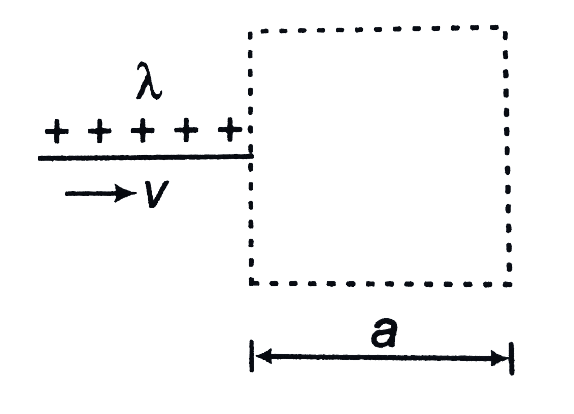
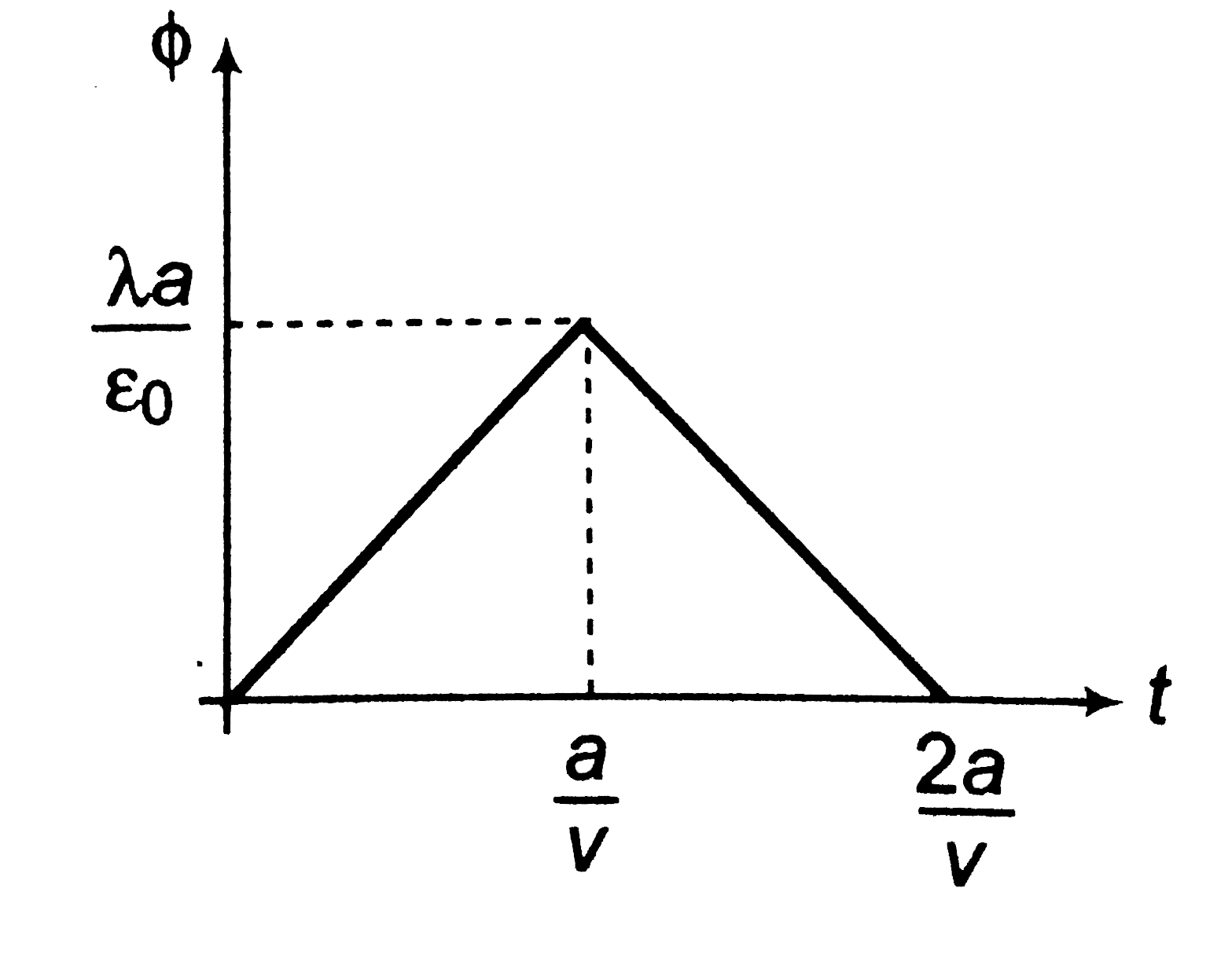
  3. Figure shows an imaginary cube of side a. A uniformly charged rod of l...

    Text Solution

    |

  4. The electric field in a region is given by E=alphaxhati. Here alpha is...

    Text Solution

    |

  5. Consider the charge configuration and a spherical Gaussian surface as ...

    Text Solution

    |

  6. A point charge q is placed on the apex of a cone of semi-vertex angle ...

    Text Solution

    |

  7. Draw E-r and V-r graphs due to two point charges + q and -2q kept at s...

    Text Solution

    |

  8. Draw E-r and V-r graphs due to two charged spherical shells as shown i...

    Text Solution

    |

  9. An electron with a speed 5.00xx10^6 m/s enters an electric field of ma...

    Text Solution

    |

  10. A charged particle of mass m=1 kg and charge q=2muC is thrown for a ho...

    Text Solution

    |

  11. Find the potential difference V(AB) between A(2m, 1m, 0) and B(0, 2m, ...

    Text Solution

    |

  12. Find potential difference V(AB) between A(0,0,0) and B(1m,1m,1m) in an...

    Text Solution

    |

  13. An electric dipole of dipole moment p is placed in a uniform electric ...

    Text Solution

    |

  14. Two identical thin ring, each of radius R meters, are coaxially placed...

    Text Solution

    |

  15. Five point charges, each of value +q coul, are placed on five vertices...

    Text Solution

    |

  16. A point charge q1=9.1muC is held fixed at origin. A second point charg...

    Text Solution

    |

  17. A point charge q1 =-5.8muC is held stationary at the origin. A second ...

    Text Solution

    |

  18. A uniformly charged thin ring has radius 10.0 cm and total charge +12....

    Text Solution

    |

  19. Two points A and B are 2 cm apart and a uniform electric field E acts ...

    Text Solution

    |

  20. An alpha particle with kinetic energy 10 Me V is heading toward a stat...

    Text Solution

    |