
Text Solution
Verified by Experts


Topper's Solved these Questions
ELECTROMAGNETIC INDUCTION
DC PANDEY|Exercise Example Type 4|2 VideosELECTROMAGNETIC INDUCTION
DC PANDEY|Exercise Example Type 5|2 VideosELECTROMAGNETIC INDUCTION
DC PANDEY|Exercise Example Type 2|2 VideosCURRENT ELECTRICITY
DC PANDEY|Exercise Medical entrances gallery|97 VideosELECTROMAGNETIC WAVES
DC PANDEY|Exercise Sec C|22 Videos
Similar Questions
Explore conceptually related problems
DC PANDEY-ELECTROMAGNETIC INDUCTION-Example Type 3
- For the ciruit shown in figure E=50V, R1=10Omega, R2=20Omega, R3=30Ome...
Text Solution
|
- An inductor of inductance L=400 mH and resistors of resistances R1=2O...
Text Solution
|
- A solenoid has an inductance of 10H and a resistance of 2Omega. It is ...
Text Solution
|
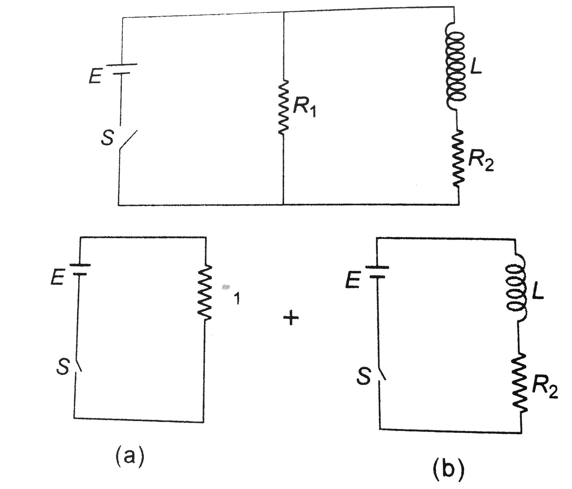
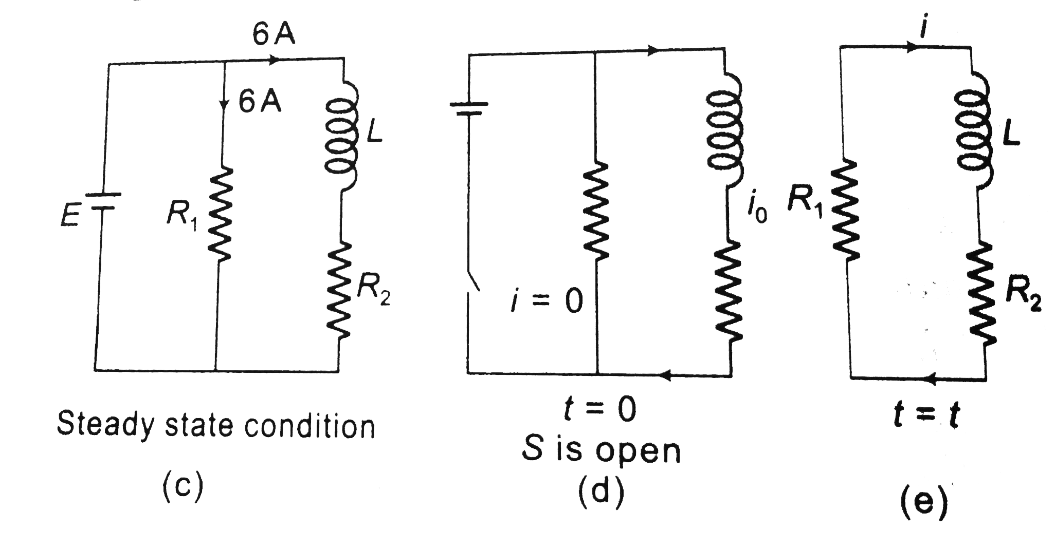
- A circuit containing a two position switch S is shown in figure a....
Text Solution
|