Home
Class 12
PHYSICS
In the circuit shown, switch S is closed...

In the circuit shown, switch `S` is closed at time `t = 0`. Find the current through the inductor as a function of time `t`.

Text Solution

Verified by Experts

The correct Answer is:
A, B, C

At `t=0`, Current through inductor will be zero.
At `t=oo` net emf `=(2//2+4//1)/(1//2+1//1)=10/3V`
Net resistance =`(2xx1)/(2+1)=2/3Omega`
`:. i=(10//3)/(2//3)=5A`

To find equivalent time constant short circuit, both the batteries and find net resistance across inductor.
`R_("net")=(2xx1)/(2+1)=2/3Omega`
`:. tau_L=L/R_("net")=(1xx10^-3)/(2/3)=3/2000s`
Current through inductor will increase exponentially from 0 to 5 A.
`:. i=5(1-e^(-(2000t)/3))`
Promotional Banner

Topper's Solved these Questions

  • ELECTROMAGNETIC INDUCTION

    DC PANDEY|Exercise Check point|60 Videos
  • ELECTROMAGNETIC INDUCTION

    DC PANDEY|Exercise Taking it together|119 Videos
  • ELECTROMAGNETIC INDUCTION

    DC PANDEY|Exercise SUBJECTIVE TYPE|1 Videos
  • CURRENT ELECTRICITY

    DC PANDEY|Exercise Medical entrances gallery|97 Videos
  • ELECTROMAGNETIC WAVES

    DC PANDEY|Exercise Sec C|22 Videos

Similar Questions

Explore conceptually related problems

In given LR circuit the switch S is closed at time t=0 then

At t=0 , switch S is closed. Find time constant of the circuit and current through inductor as a function of time t .

In the circuit shown in figure switch S is closed at time t=0 Takin left to right current through the indcutor as apositive current, current through inductor varies with time as

In the circuit shown if Fig. the switch S is closed at time t = 0. The current through the capacitor and inductor will be equal at time t equal (given R = sqrt(L//C)

In the circuit arrangement shown in figure, the switch S is closed at t = 0 . Find the current in the inductance as a function of time? Does the current through 10 Omega resistor vary with time or remains constant.

In the circuit shown, the switch 'S' is closed at t = 0 . Then the current through the battery steady state reached is

In the circuit shown in figure-3.240 switch S is closed at time t=0. find the current through different wires and charge stored on the capacitor at any time t.

In the circuit shown in the figure, switch S is closed at time t = 0 . (a) Write current in the circuit and charge on capacitor as a function of time. Draw the graphical plot for the same. (b) Find maximum charge on the capacitor. What is potential difference across the inductor when charge on the capacitor is maximum?

In the circuit shown in the figure, switch S is closed at time t=0 . Select the correct statements.

DC PANDEY-ELECTROMAGNETIC INDUCTION-Level 2 Subjective
  1. A rectangular loop with a sliding connector of length l is located in ...

    Text Solution

    |

  2. A rod of length 2a is free to rotate in a vertical plane, about a hori...

    Text Solution

    |

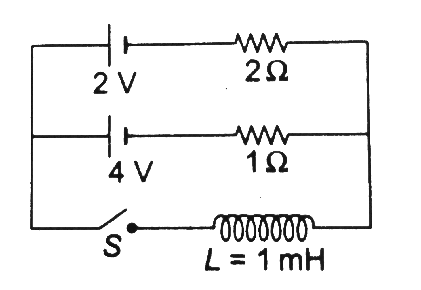
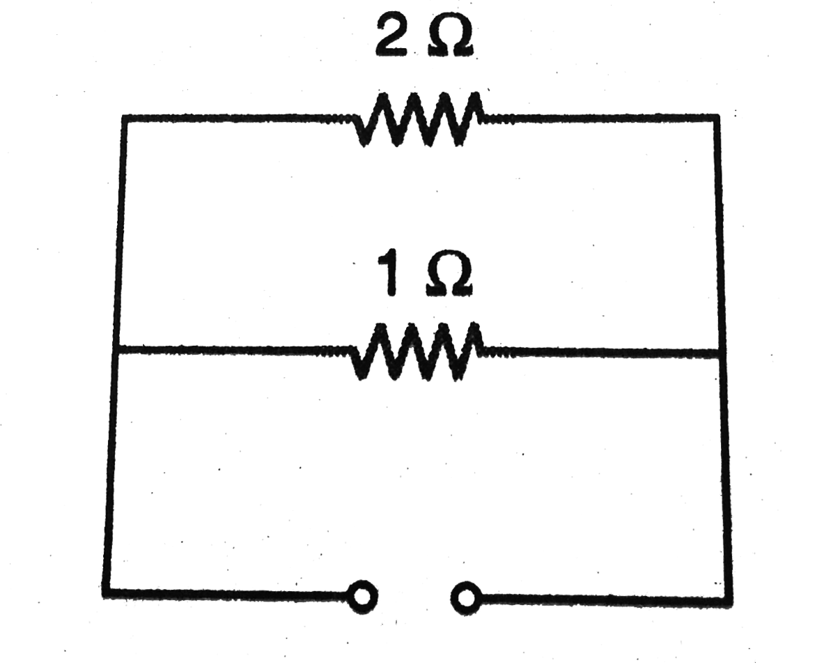
  3. In the circuit arrangement shown in figure, the switch S is closed at ...

    Text Solution

    |

  4. In the circuit shown, switch S is closed at time t = 0. Find the curre...

    Text Solution

    |

  5. In the circuit shown in figure, E = 120 V, R1 = 30.0Omega, R2 = 50.0 O...

    Text Solution

    |

  6. Two capacitors of capacitances 2C and C are connected in series with a...

    Text Solution

    |

  7. A 1.00 mH inductor and a 1.00muF capacitor are connected in series. Th...

    Text Solution

    |

  8. In the circuit shown in the figure, E = 50.0 V, R = 250 Omega and C = ...

    Text Solution

    |

  9. The conducting rod ab shown in figure makes contact with metal rails c...

    Text Solution

    |

  10. A non-conducting ring of mass m and radius R has a charge Q uniformly ...

    Text Solution

    |

  11. Two parallel long smooth conducting rails separated by a distance l ar...

    Text Solution

    |

  12. A circuit containing capacitors C1 and C2, shown in the figure is in t...

    Text Solution

    |

  13. Initially, the capacitor is charged to a potential of 5 V and then con...

    Text Solution

    |

  14. A rod of mass m and resistnce R sldes on frictionless and resistancele...

    Text Solution

    |

  15. Two metal bars are fixed vertically and are connected on the top by a ...

    Text Solution

    |

  16. A conducting light string is wound on the rim of a metal ring of radiu...

    Text Solution

    |

  17. A conducting frame abcd is kept in a vertical plane. A conducting rod ...

    Text Solution

    |

  18. A rectangular loop with a sliding conductor of length l is located in ...

    Text Solution

    |

  19. A conducting circular loop of radius a and resistance per unit length ...

    Text Solution

    |

  20. U-frame ABCD and a sliding rod PQ of resistance R, start moving with v...

    Text Solution

    |