Text Solution
Verified by Experts
The correct Answer is:
 .
.


Topper's Solved these Questions
Similar Questions
Explore conceptually related problems
DC PANDEY-SEMICONDUCTORS-Subjective
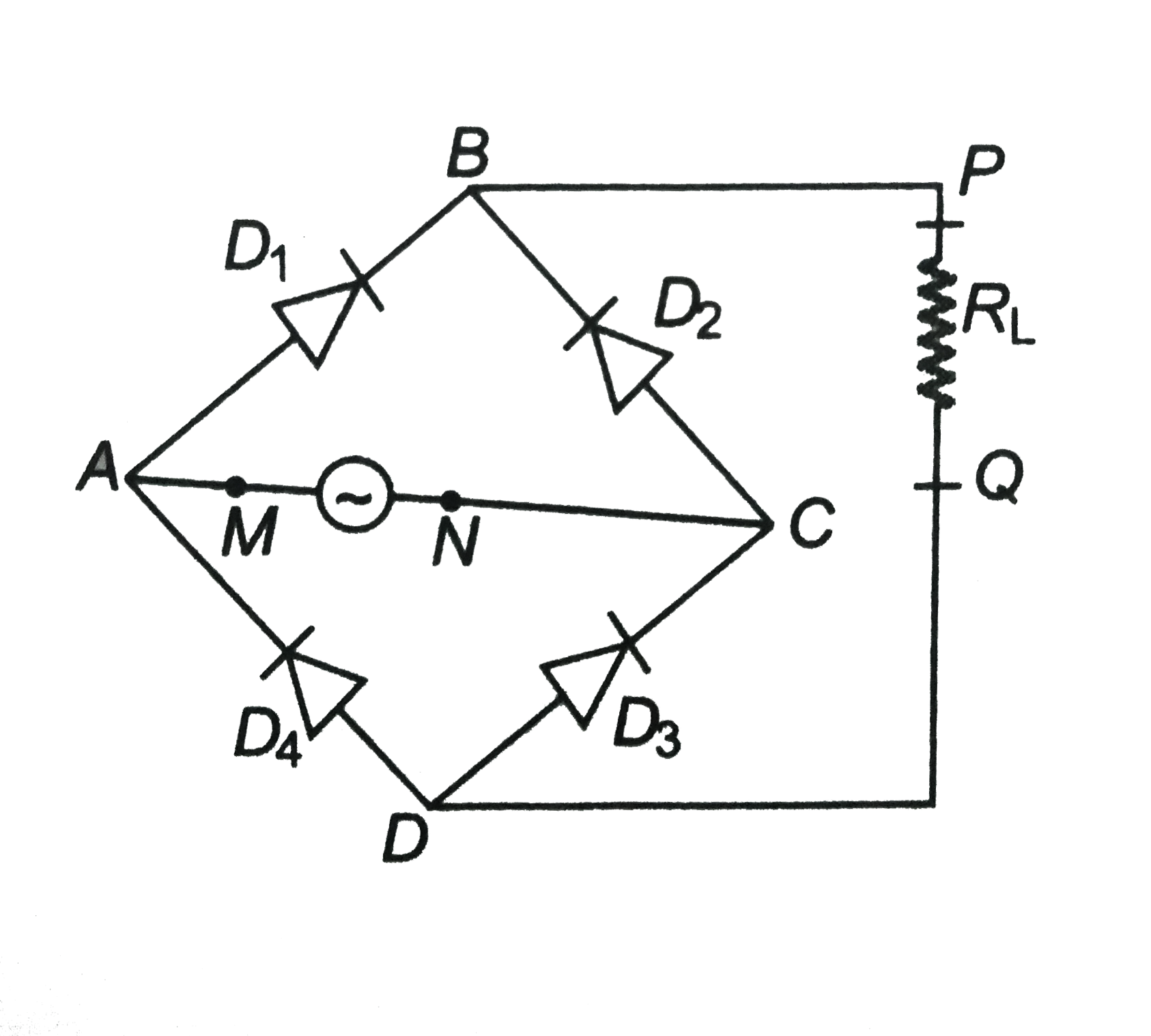
- In the figure, the input is across the terminals A and C and the o...
Text Solution
|
- Can the potential barrier across a p-n junction be measured by simply ...
Text Solution
|
- Two car garages have a common gate which needs to open automatically w...
Text Solution
|
- Two amplifiers are connected one after the other in series (cascaded)....
Text Solution
|
- A p-n junction is fabricated from a semiconductor with band gap of 2.8...
Text Solution
|
- (i) Name the type of a diode whose characteristic are shown figure . (...
Text Solution
|
- If the resistance R1 is increased , how will the readings of the ammet...
Text Solution
|
- How would you set up a circuit to obtain NOT gate using a transistor?
Text Solution
|
- A Zener of power rating 1 W is to be used as a voltage regulator. If ...
Text Solution
|
- If each diode in figure has a forward has a forward bias resistance of...
Text Solution
|
- In the circuit shown in figure when the input voltage of the base resi...
Text Solution
|
- For the transistor circuit shown in figure , evaluate VE , RB and RE. ...
Text Solution
|
- In the circuit shown in figure , find the value of RC.
Text Solution
|