


Similar Questions
Explore conceptually related problems
Recommended Questions
- In the circuit shown in Fig.a voltage V is connected across lamp L. Wh...
Text Solution
|
- The resistance of the filament of a lamp increases with the increase i...
Text Solution
|
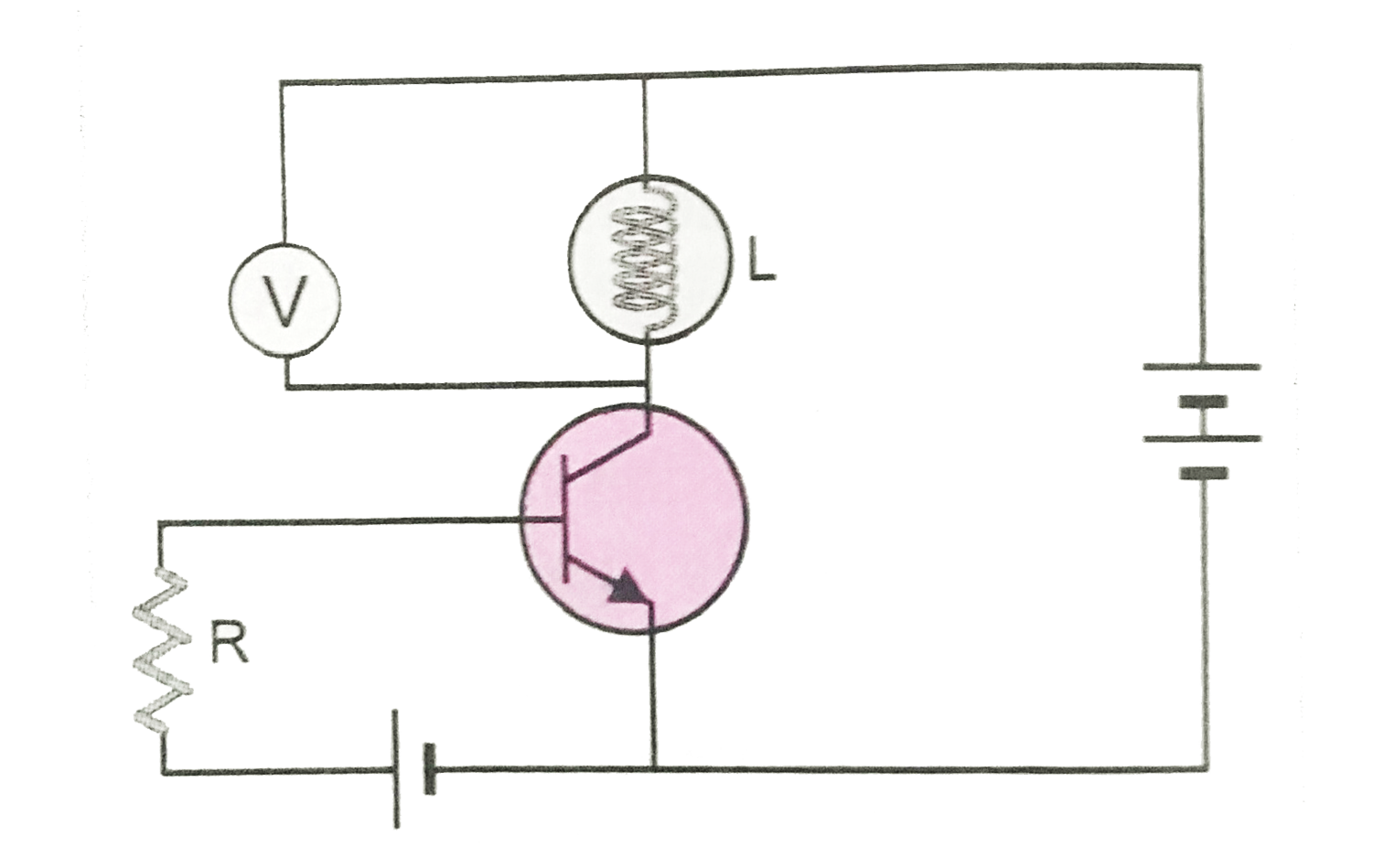
- In the following circuit, a voltmeter V is connected across a lamp L ....
Text Solution
|
- In the circuit shown in Fig.a voltage V is connected across lamp L. Wh...
Text Solution
|
- In a series L-C-R circuit the voltage across resistance , capacitance ...
Text Solution
|
- In the given circuit diagram, a voltmeter 'V' is connected across a la...
Text Solution
|
- In an electric circuit, potential difference across a lamp is 20 V and...
Text Solution
|
- In an L-C-R circuit, if V is the effective value of the applied voltag...
Text Solution
|
- In the given circuit diagram, a voltmeter 'V' is connected across a la...
Text Solution
|