A
B
C
D
Text Solution
Verified by Experts
The correct Answer is:


Topper's Solved these Questions
CURRENT ELECTRICITY
MHTCET PREVIOUS YEAR PAPERS AND PRACTICE PAPERS|Exercise EXERCISE 2|26 VideosCURRENT ELECTRICITY
MHTCET PREVIOUS YEAR PAPERS AND PRACTICE PAPERS|Exercise MHT CET CORNER|32 VideosCURRENT ELECTRICITY
MHTCET PREVIOUS YEAR PAPERS AND PRACTICE PAPERS|Exercise MHT CET CORNER|32 VideosCOMMUNICATION SYSTEM
MHTCET PREVIOUS YEAR PAPERS AND PRACTICE PAPERS|Exercise MHC CET Corner|6 VideosELASTICITY
MHTCET PREVIOUS YEAR PAPERS AND PRACTICE PAPERS|Exercise MHT CET CORNER|16 Videos
Similar Questions
Explore conceptually related problems
MHTCET PREVIOUS YEAR PAPERS AND PRACTICE PAPERS-CURRENT ELECTRICITY-EXERCISE 1
- Figure shows a circuit with known resistances R(1) and R(2) . Neglect ...
Text Solution
|
- The potential difference across the terminals of a battery is 50 V whe...
Text Solution
|
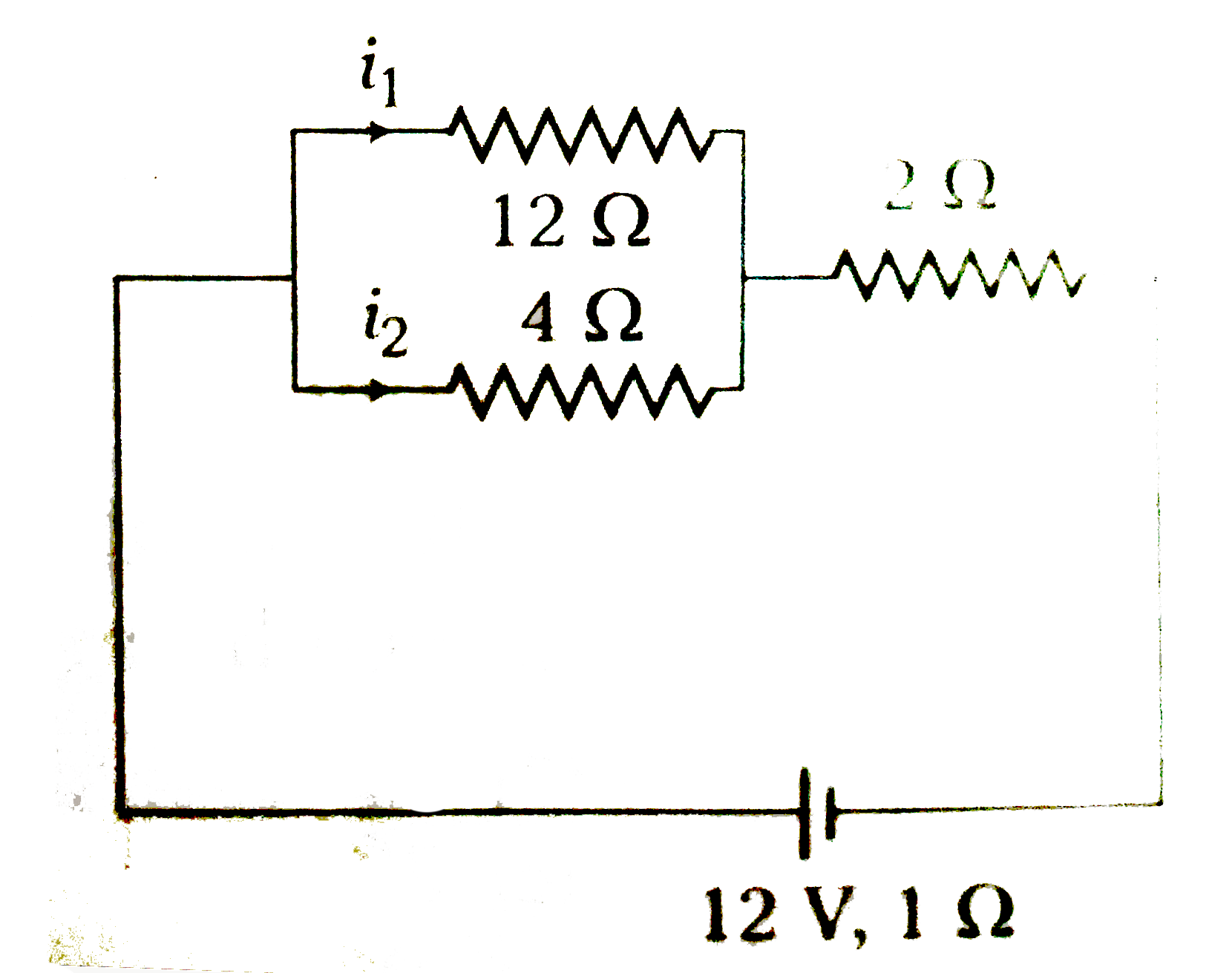
- In the circuit shown, the currents i(1) and i(2) are
Text Solution
|
- A battery of emf 10 V and internal resistance 3Omegais connected to a ...
Text Solution
|
- In the following circuit reading of voltmeter V is
Text Solution
|
- In the electric circuit shown each cell has an emf of 2 V and internal...
Text Solution
|
- Five conductors are meeting a point x as shown in the figures . What i...
Text Solution
|
- Two resistors of resistances 2Omega and 6Omega are connected in parall...
Text Solution
|
- Four identical cells of emf epsilon and internal resistance r are to b...
Text Solution
|
- Two cells having an internal resistance of 0.2 Omega and 0.4 Omega are...
Text Solution
|
- Two cells of emf E(1) and E(2) are joined in opposition (such that E(1...
Text Solution
|
- A circuit consists of three bateries of emf E(1) = 1V, E(2)=2V and E(3...
Text Solution
|
- Two identical cells whether connected in parallel or in series gives t...
Text Solution
|
- The current pasing through the ideal ammeter in the circuit given belo...
Text Solution
|
- In a typical wheatstone network the resistance in cyclic order are A=1...
Text Solution
|
- In a potentiometer experiment for measuring the emf of cell, the null ...
Text Solution
|
- In a Wheatstone's network, P=2Omega, Q=2Omega, R=2Omega and S=3Omega. ...
Text Solution
|
- In a potentiometer experiment the balancing with a cell is at length 2...
Text Solution
|
- For measurement of potential difference, potentiometer is perferred in...
Text Solution
|
- Five resistance are connected as shown in the figure . The equivalent ...
Text Solution
|