A
B
C
D
Text Solution
Verified by Experts
The correct Answer is:


Topper's Solved these Questions
SEMICONDUCTORS
MHTCET PREVIOUS YEAR PAPERS AND PRACTICE PAPERS|Exercise Exercise 1 ( MISCELLANEOUS PROBLEMS )|33 VideosSEMICONDUCTORS
MHTCET PREVIOUS YEAR PAPERS AND PRACTICE PAPERS|Exercise MHT CET Corner|25 VideosSEMICONDUCTORS
MHTCET PREVIOUS YEAR PAPERS AND PRACTICE PAPERS|Exercise MHT CET Corner|25 VideosSCALARS AND VECTORS
MHTCET PREVIOUS YEAR PAPERS AND PRACTICE PAPERS|Exercise Exercise 2 (Miscellaneous Problems)|20 VideosSTATIONARY WAVES
MHTCET PREVIOUS YEAR PAPERS AND PRACTICE PAPERS|Exercise MHT CET Corner|28 Videos
Similar Questions
Explore conceptually related problems
MHTCET PREVIOUS YEAR PAPERS AND PRACTICE PAPERS-SEMICONDUCTORS-Exercise 1 ( TOPICAL PROBLEMS )
- The voltage gain of an amplifier with 9% negative feedback is 10. The ...
Text Solution
|
- The minimum potential difference between the base and emitter required...
Text Solution
|
- In the CB mode of a transistor, when the collector voltage is changed ...
Text Solution
|
- Symbolic representation of four logic gates are shown as
Text Solution
|
- Symbolic representation of NOR gate is
Text Solution
|
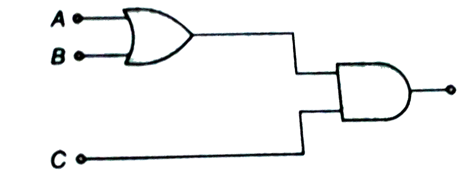
- The output of given logic circuit is
Text Solution
|
- To get an output 1 from the circuit shown in the figure, the input mus...
Text Solution
|
- The circuit is equivalent to
Text Solution
|
- The output y, when all three inputs are first high and then low, will ...
Text Solution
|
- An AND gate is following by a NOT gate in series. With two inputs A & ...
Text Solution
|
- Which logic gate is represented by the following combination of logic ...
Text Solution
|
- To which logic gate does the truth table given below correspond ?
Text Solution
|
- In Boolean algebra A + B = Y implies that :
Text Solution
|
- Digital circuit can be made by repetitive use of
Text Solution
|
- If A = B = 1, then in terms of Boolean algebra the value of A.B + A is...
Text Solution
|
- For the given combination of gates, if the logic states of inputs A,B,...
Text Solution
|
- Which of the following gates will have an output of 1
Text Solution
|
- What will be the input of A and B for the Boolean expression bar((A+B)...
Text Solution
|
- To get an output 1 from the circuit shown in the figure, the input mus...
Text Solution
|
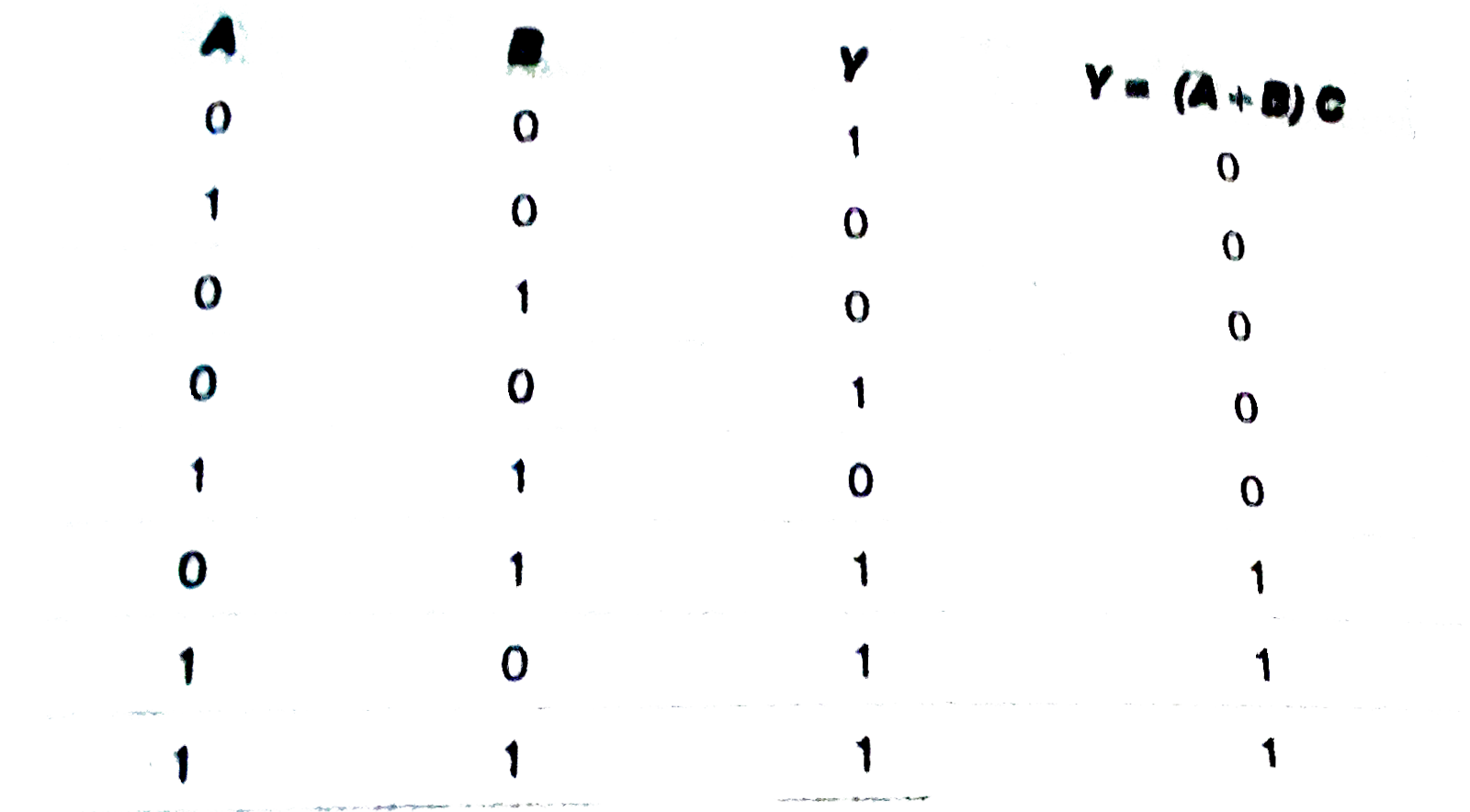
- Which of the following is the truth table for the circuit below ?
Text Solution
|