A
B
C
D
Text Solution
Verified by Experts
The correct Answer is:


Topper's Solved these Questions
SEMICONDUCTORS
MHTCET PREVIOUS YEAR PAPERS AND PRACTICE PAPERS|Exercise MHT CET Corner|25 VideosSEMICONDUCTORS
MHTCET PREVIOUS YEAR PAPERS AND PRACTICE PAPERS|Exercise Exercise 1 ( TOPICAL PROBLEMS )|84 VideosSCALARS AND VECTORS
MHTCET PREVIOUS YEAR PAPERS AND PRACTICE PAPERS|Exercise Exercise 2 (Miscellaneous Problems)|20 VideosSTATIONARY WAVES
MHTCET PREVIOUS YEAR PAPERS AND PRACTICE PAPERS|Exercise MHT CET Corner|28 Videos
Similar Questions
Explore conceptually related problems
MHTCET PREVIOUS YEAR PAPERS AND PRACTICE PAPERS-SEMICONDUCTORS-Exercise 1 ( MISCELLANEOUS PROBLEMS )
- In a common-base amplifier, the phase difference between the input sig...
Text Solution
|
- In an n-p-n transistor circuit, the collector current is 9 mA. If 90% ...
Text Solution
|
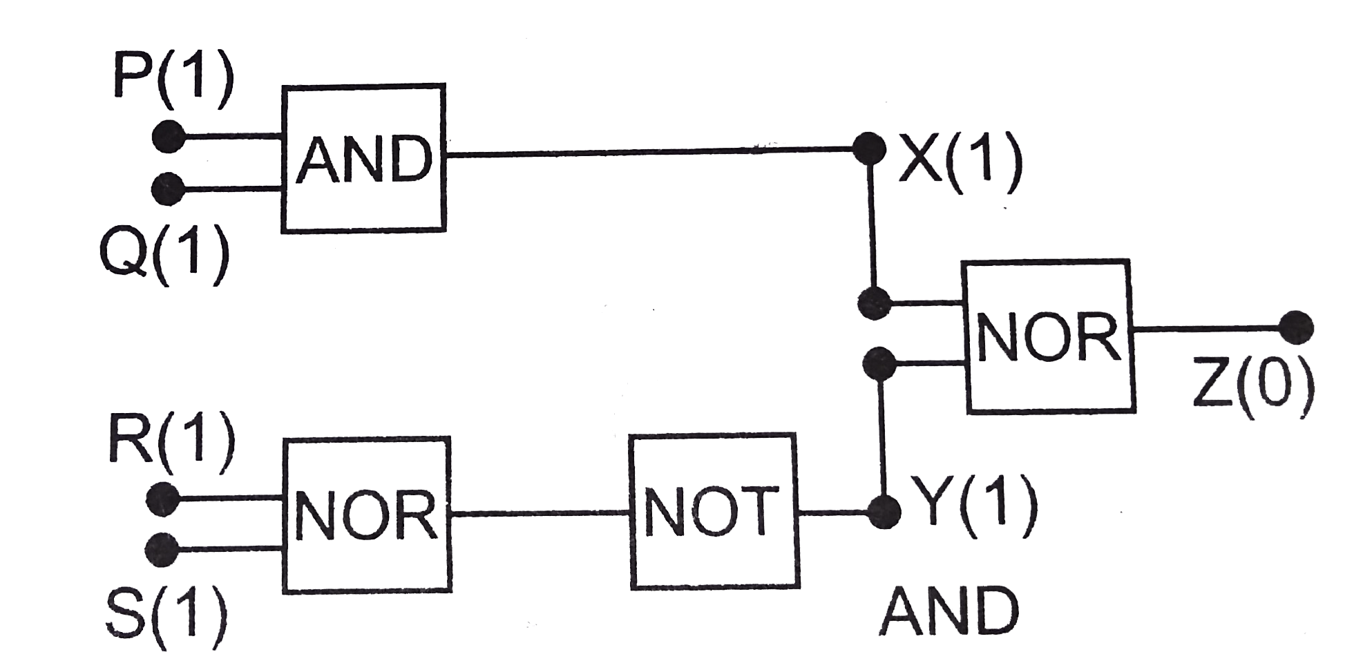
- The circuit diagram (see fig.) shows a 'logic combination' with the st...
Text Solution
|
- The combination of gates shown below yields
Text Solution
|
- The input resistance of a silicon transistor is 100Omega base current ...
Text Solution
|
- Pure sodium (Na) is a good conductor of electricity because the 3s and...
Text Solution
|
- In a common base amplifier circuit, calculate the change in base curre...
Text Solution
|
- In the figure, potential difference between A and B is
Text Solution
|
- The circuit shown in the figure contains two diodes each with a forwar...
Text Solution
|
- The diode used in the circuit shown in the figure has a constant volta...
Text Solution
|
- In a common emitter amplifier, using output reisistance of 5000 ohm an...
Text Solution
|
- The length of a germanium rod is 0.58 cm and its area of cross-section...
Text Solution
|
- If a Zener diode (V(Z)=5 and I(Z)=10 mA) is connected in series with a...
Text Solution
|
- A red LED emits light of 0.1 watt uniformaly around it. The amplitude ...
Text Solution
|
- The circuit has two oppositively connected ideal diodes in parallel wh...
Text Solution
|
- A 2V battery is connected across AB as shown in the figure. The value ...
Text Solution
|
- The value of the resistor, R(S), needed in the dc voltage regulator ci...
Text Solution
|
- An LED is constructed from a p-n junction based on a certain semi-cond...
Text Solution
|
- In a triode, gm=2xx10^(-3)ohm^(-1) , mu=42, resistance load, R = 50 ki...
Text Solution
|
- The input characteristics of a transistor in CE mode is the graph obta...
Text Solution
|