 .
. Text Solution
Verified by Experts
 .
.  .
. 


Topper's Solved these Questions
CAPACITOR AND CAPACITANCE
CENGAGE PHYSICS|Exercise Exercise 4.1|13 VideosCAPACITOR AND CAPACITANCE
CENGAGE PHYSICS|Exercise Exercise 4.2|32 VideosCAPACITOR AND CAPACITANCE
CENGAGE PHYSICS|Exercise Integer|5 VideosATOMS
CENGAGE PHYSICS|Exercise QUESTION BANK|40 VideosCENGAGE PHYSICS DPP
CENGAGE PHYSICS|Exercise subjective type|51 Videos
Similar Questions
Explore conceptually related problems
CENGAGE PHYSICS-CAPACITOR AND CAPACITANCE-Solved Examples
- The figure shows two identical parallel plate capacitors connected to ...
Text Solution
|
- Two parallel plate capacitors of capacitance C each are connected in s...
Text Solution
|
- Five identical conducting plates, 1, 2,3,4 and 5 are fixed parallel pl...
Text Solution
|
- Two parallel plate capacitors A and B have the same separation d=8.85x...
Text Solution
|
- Two capacitors A and B with capacities 3 muF and 2 muF are charged to ...
Text Solution
|
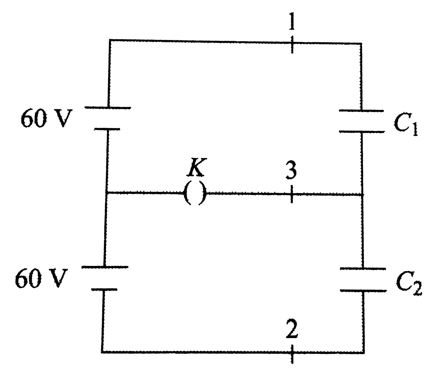
- In the circuit shown , the emf of each battery is 60 V and C(1)=2 muF ...
Text Solution
|
- Find the capacitance between the terminals A and C(3) If epsilon(r) = ...
Text Solution
|
- Two parallel plate capacitors differ only in the spacing between their...
Text Solution
|
- In, all the capacitors are in steady state initially. i. What is the...
Text Solution
|
- In the circuit shown in , capacitor A has capacitance C(1)=2 muF when ...
Text Solution
|