Text Solution
Verified by Experts


Topper's Solved these Questions
ELECTRIC CURRENT AND CIRCUIT
CENGAGE PHYSICS|Exercise Subjective|29 VideosELECTRIC CURRENT AND CIRCUIT
CENGAGE PHYSICS|Exercise Single Correct|72 VideosELECTRIC CURRENT AND CIRCUIT
CENGAGE PHYSICS|Exercise Exercise 5.1|28 VideosELECTRIC CURRENT & CIRCUITS
CENGAGE PHYSICS|Exercise Kirchhoff s law and simple circuits|15 VideosELECTRIC FLUX AND GAUSS LAW
CENGAGE PHYSICS|Exercise MCQ s|38 Videos
Similar Questions
Explore conceptually related problems
CENGAGE PHYSICS-ELECTRIC CURRENT AND CIRCUIT-Exercise 5.2
- How a battery is to be connected so that the shown rheostat will behav...
Text Solution
|
- In the following circuit ,E1 = 4V, R1 = 2 Omega, E2 = 6 V, R2 = 2Oem...
Text Solution
|
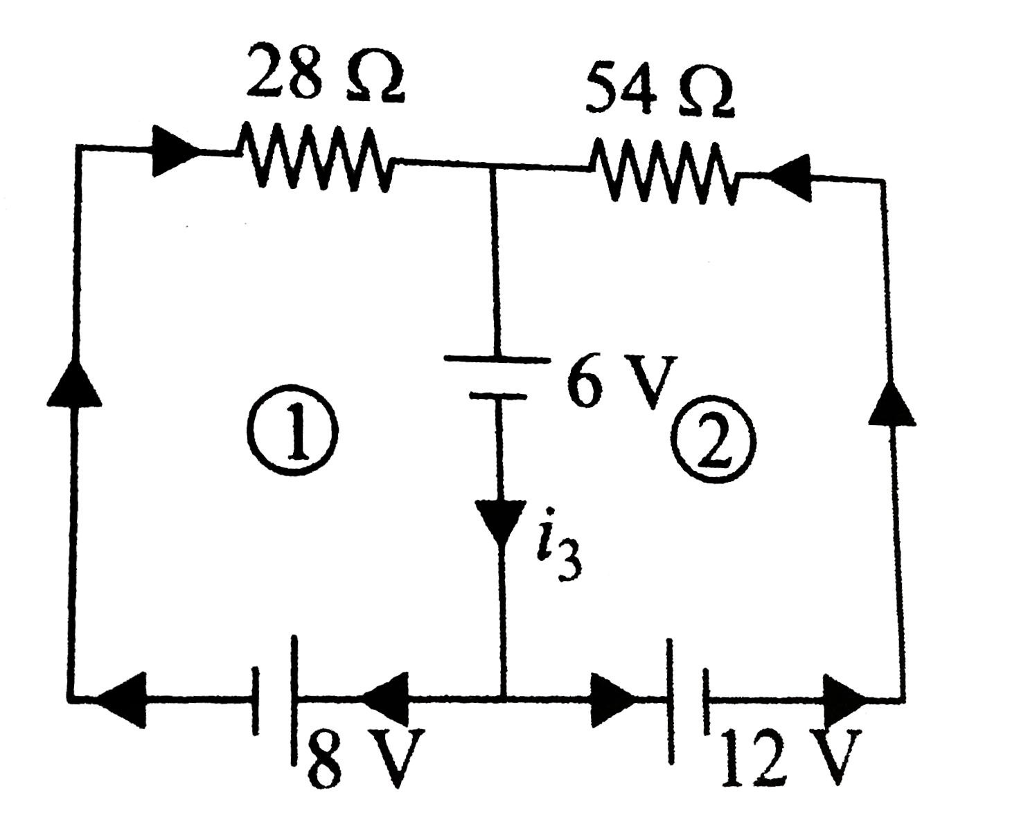
- Consider the cicutir shown in fig. the current i3 is equal to
Text Solution
|
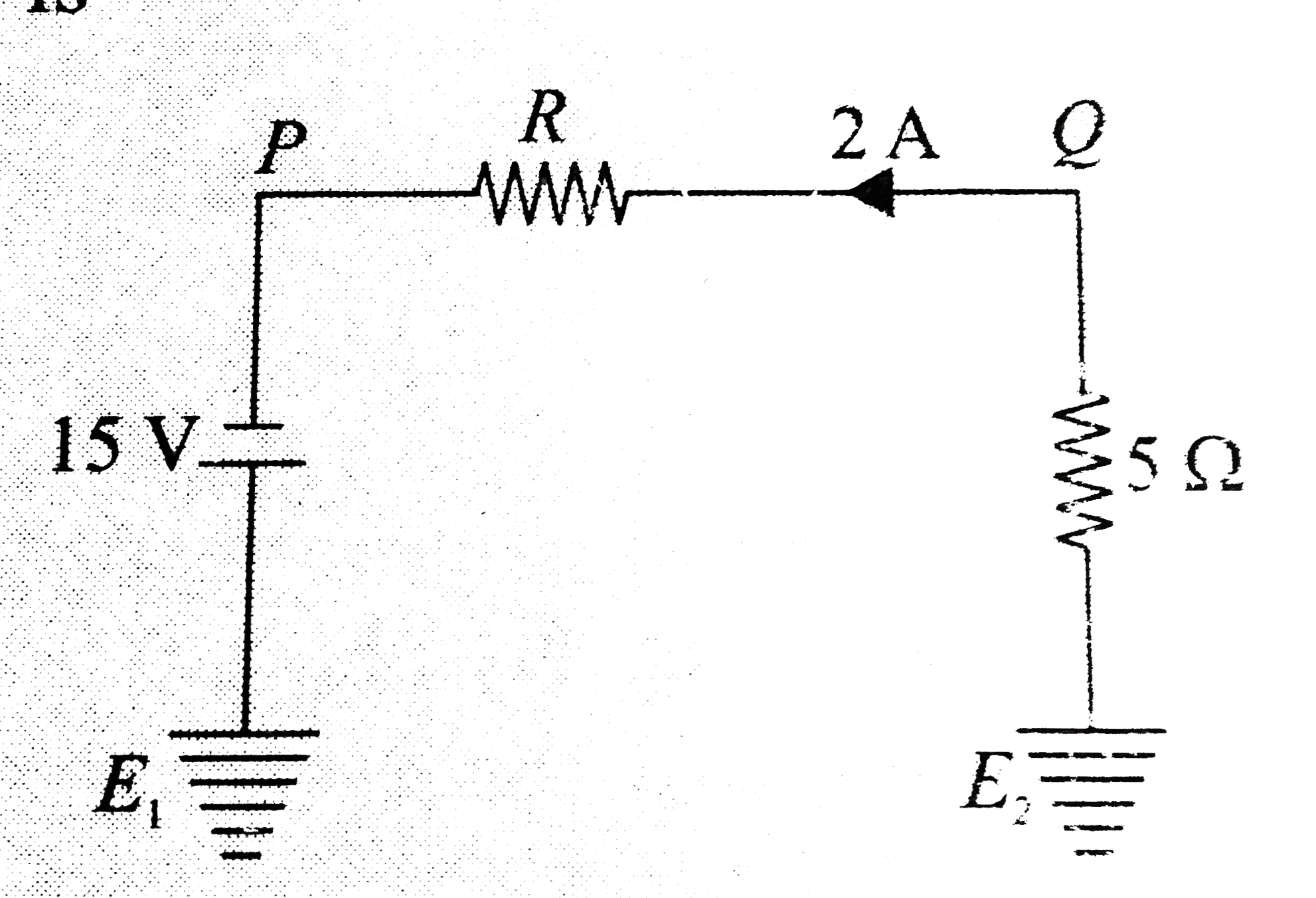
- In the follwing circuit , the potential difference betweenn P and Q si
Text Solution
|
- Find the current in each wire.
Text Solution
|
- in the network of three cells, find the potential V of their funcion.
Text Solution
|
- consider the ciruict shown in fig. The current thorugh the 6 Omega res...
Text Solution
|
- In the circuit shown in fig the voltage across the 2Omega resistor is ...
Text Solution
|
- In the circuit shown in fig a. find the current in resistor R b. f...
Text Solution
|
- In the circuit shown in figure find: a. the current in the 3.00 Om...
Text Solution
|
- In the circuit shown in figure , a. find the current is each branch ...
Text Solution
|
- Consider the circuit shown in fig. If the switch is closed at t =0, th...
Text Solution
|
- Shown three sections of the circuit that are to be connecte in turn to...
Text Solution
|
- Determine the current through the battery in the circuit shown in figu...
Text Solution
|
- A varying voltage is applied to the clamps AB as shown in fig. such th...
Text Solution
|
- Consider the network shown in initially, the switch S(1) is closed and...
Text Solution
|
- In the circuit shown in fig. R(1) = 10 Omega, R(2) = Omega, C(1) = 1 m...
Text Solution
|
- In the circuit shown in fig switch S is closed at time t =0. a. ...
Text Solution
|
- The plates of a 50(mu)F capacitor charged to 400(mu)C are connected th...
Text Solution
|
- The electric field between the plates of a parallel-plate capacitor of...
Text Solution
|