Home
Class 12
PHYSICS
Shown two ideal voltmeters and an ammete...

Shown two ideal voltmeters and an ammeter, which are connected across the various circuit elements. If the voltmeter connected across `9Omega` resistance reads 4.5 V, then answer the following problems.

The reading of the voltmeter connected across `20Omega` resistance is

A

15V

B

10V

C

5V

D

`22.5V`

Text Solution

Verified by Experts

The correct Answer is:
A


`I_(1) = (4.5)/(9) = (1)/(2)A`
Potential difference across AB:
`4.5 +3I_(1) = 6I_(2) or I_(2) = 1 A, I = I_(1) + I_(2) = 1.5A`
Equivalent resistance between C and D: `R_(1) =4Omega`
Potential difference across `CD : R_(1) I = 4xx1.5 =6V`
Current through `12Omega, I_(3) = (6)/(12) = (1)/(2)A`
Potential difference across AD is
`6I_(2) +2I +12I_(3) = 6xx1+2xx1.5+12 xx0.5 =15V`
This will be equal to the reading of voltmeter across `20Omega`
`I_(4) = (15)/(20) = 0.75A`
Reading of the ammeter is `I +I_(4) =1.5 + 0.75 = 2.25A`
Promotional Banner

Topper's Solved these Questions

  • ELECTRIC CURRENT AND CIRCUIT

    CENGAGE PHYSICS|Exercise Interger|8 Videos
  • ELECTRIC CURRENT AND CIRCUIT

    CENGAGE PHYSICS|Exercise Multiple Correct|16 Videos
  • ELECTRIC CURRENT & CIRCUITS

    CENGAGE PHYSICS|Exercise Kirchhoff s law and simple circuits|15 Videos
  • ELECTRIC FLUX AND GAUSS LAW

    CENGAGE PHYSICS|Exercise MCQ s|38 Videos

Similar Questions

Explore conceptually related problems

Shown two ideal voltmeters and an ammeter, which are connected across the various circuit elements. If the voltmeter connected across 9Omega resistance reads 4.5 V, then answer the following problems. The reading of the ammeter is

Shown two ideal voltmeters and an ammeter, which are connected across the various circuit elements. If the voltmeter connected across 9Omega resistance reads 4.5 V, then answer the following problems. The current through 12Omega resistance is

In the given circuit, an ideal voltmeter connected across the 10Omega resistance reads 2V. The internal resistance r, of each cell is:

In Fig. 6.59 , when an ideal voltmetre is connected across 4000 Omega resistance, it reads 30 V . If the voltmeter is connected across 3000 Omega resistance, it will read

In the circuit given below, a voltmeter reads 20V when it is connected across 400Omega resistance. Calculate what the same voltmeter will read when connected across the 200Omega resistance.

In the circuit shown, reading of the voltmeter connected across 400 Omega resistance is 60 V. If it is connected across 300 Omega resistance then reading in volt will be

In the circuit shown in figure-3 .3 89, the voltmeter reads 30V when it is connected across 400 Omega resistance. Calculate what the same voltmeter will read when it is connected across the 300 Omega resistance.

A voltmeter of resistance 1000 Omega is connected across a resistance of 500 Omega in the given circuit. What will be the reading of voltmeter

In the circuit, a voltmeter reads 30 V when it is connected across 400 Omega resistance. Calculate what the same voltmeter will read when it is connected across the 300Omega resistance?

CENGAGE PHYSICS-ELECTRIC CURRENT AND CIRCUIT-Comprehension
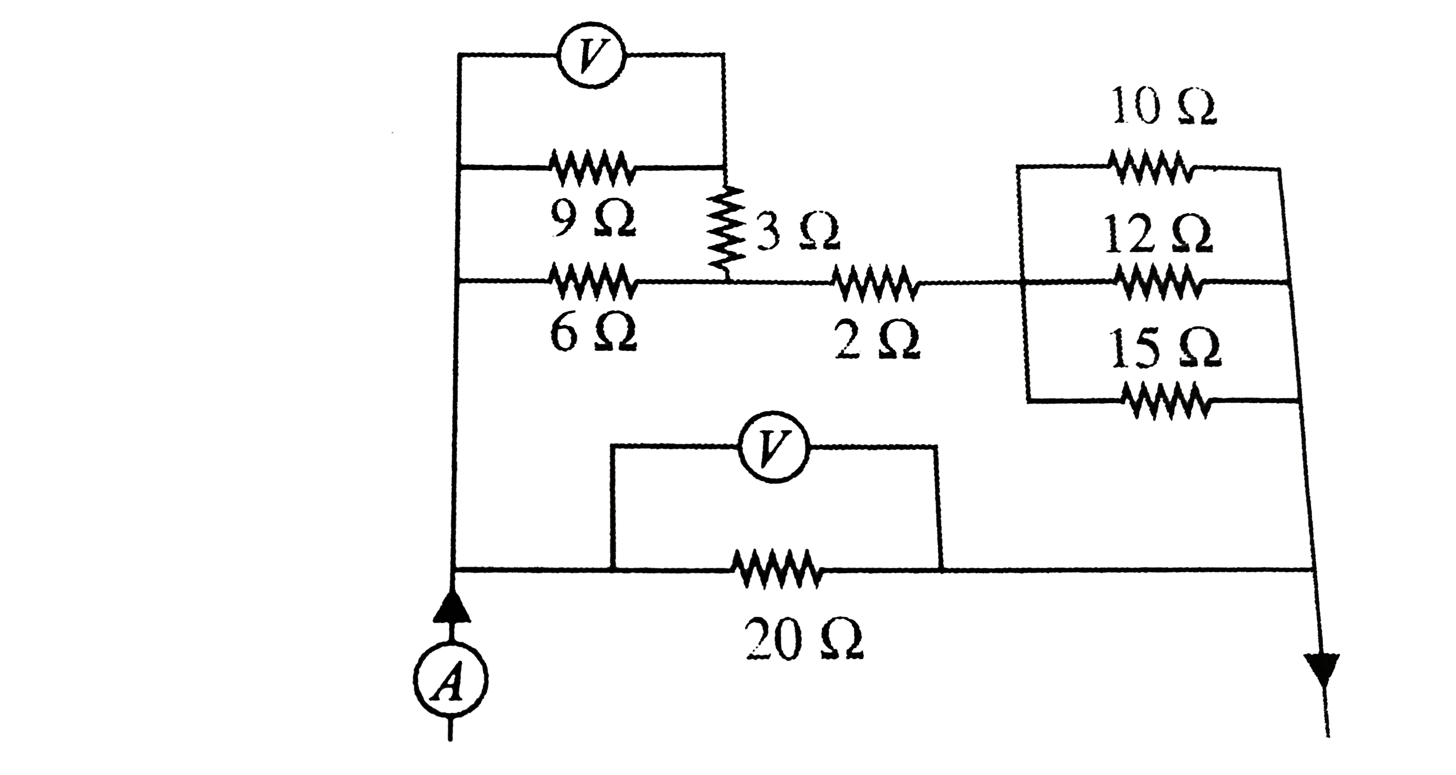
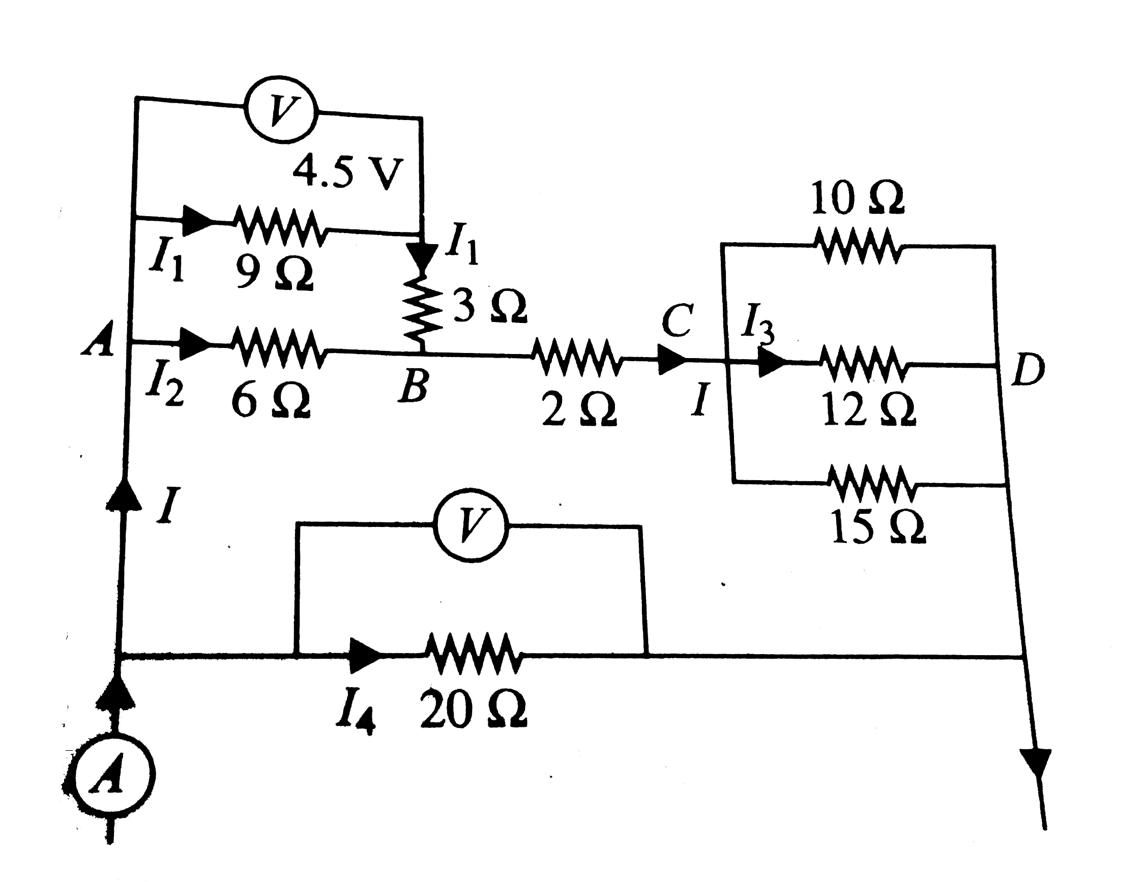
  1. Find the current supplied by battery in the cirucit in each case (a),(...

    Text Solution

    |

  2. Shown two ideal voltmeters and an ammeter, which are connected across ...

    Text Solution

    |

  3. Shown two ideal voltmeters and an ammeter, which are connected across ...

    Text Solution

    |

  4. Shown two ideal voltmeters and an ammeter, which are connected across ...

    Text Solution

    |

  5. A network of resistance is constructed with R1 and R2 as shown in fig....

    Text Solution

    |

  6. A network of resistance is constructed with R1 and R2 as shown in fig....

    Text Solution

    |

  7. A network of resistance is constructed with R1 and R2 as shown in fig....

    Text Solution

    |

  8. Relation between current in a conductor and time is shown in fig. ...

    Text Solution

    |

  9. Relation between current in a conductor and time is shown in fig. ...

    Text Solution

    |

  10. Relation between current in a conductor and time is shown in fig. ...

    Text Solution

    |

  11. Consider the circuit shwon in fig. The circuit is in steady state. ...

    Text Solution

    |

  12. Consider the circuit shwon in fig. The circuit is in steady state. ...

    Text Solution

    |

  13. Consider the circuit shwon in fig. The circuit is in steady state. ...

    Text Solution

    |

  14. In the netwrok shown in fig. each resistance is R. The equivalent...

    Text Solution

    |

  15. In the netwrok shown in fig. each resistance is R. The equivalent...

    Text Solution

    |

  16. In the netwrok shown in fig. each resistance is R. The equivalent...

    Text Solution

    |

  17. A resistor circuit is constructed such that 12 resistor are arranged t...

    Text Solution

    |

  18. A resistor circuit is constructed such that 12 resistor are arranged t...

    Text Solution

    |

  19. A resistor circuit is constructed such that 12 resistor are arranged t...

    Text Solution

    |

  20. Consider 12 resistor arranged symmetrically in shape of bipyraimd ABCD...

    Text Solution

    |