Home
Class 12
PHYSICS
A, B and C are voltmeters of resistances...

`A, B` and `C` are voltmeters of resistances `R, 1.5R` and `3R` respectively. When some potential difference is applied between `x` and `y` the voltmeter readings are `V_A, V`_B`and `V_C,` then

A

`V_(A) = V_(B) = V_(C)`

B

`V_(A) != V_(B) = V_(C)`

C

V_(A) = V_(B) != V_(C)`

D

V_(B) != V_(A) = V_(C)`

Text Solution

Verified by Experts

The correct Answer is:
A

`V_(B) = iR`,
`V_(B) = (2i)/(3) xx 1.5 R = iR`, `V_(C) = (i//3)(3R) = iR`
Promotional Banner

Topper's Solved these Questions

  • ELECTRICAL MEASURING INSTRUMENTS

    CENGAGE PHYSICS|Exercise Multiple Correct|7 Videos
  • ELECTRICAL MEASURING INSTRUMENTS

    CENGAGE PHYSICS|Exercise Assertion-Reasoning|7 Videos
  • ELECTRICAL MEASURING INSTRUMENTS

    CENGAGE PHYSICS|Exercise Subjective|18 Videos
  • ELECTRIC POTENTIAL

    CENGAGE PHYSICS|Exercise DPP 3.5|14 Videos
  • ELECTROMAGENTIC INDUCTION

    CENGAGE PHYSICS|Exercise QUESTION BANK|40 Videos

Similar Questions

Explore conceptually related problems

A,B and C are voltmeters of resistance R, 1.5 R and 3R respectively as shown in the figure. When some potential difference is applied between X and Y, the voltmeter reading are V_A , V_B and V_C respectively.

Three voltmeters A, B and C having resistances R, 1.5 R and 3 R respectively are used in a circuit as shown. When a potential difference is applied between X and Y, the readings of the voltmeters are V_1, V_2 and V_3 respectively. Then :

Three voltmeters all having different resistance, are joined as shown. When some potential difference is applied acros A and B , their readings are V_1,V_2 and V_3. Then

In the circuit shownin figure V_1 and V_2 are two voltmeter of resistances 3000 Omega and 2000 Omega respectively. In additions R_1=2000Omega , R_2=3000omega and E=200 V then a. Fid the reading of voltmeters V_1 and V_2 when i. switch S is open ii. Switch S is closed b. Current through S , when it is closed (Disregard the resistance of battery)

If the potential difference between A and D is V, what will be potential difference between F and C. each of the resistance is R.

An ammeter A, a voltmeter V and a resistance R are connected as shown in the figure. If the voltmeter reading is 1.6V and the ammeter reading is 0.4 A, then R is

An ammeter and a voltmeter of resistance R are connected in series to an electric cell of negligible internal resistance . Their readings are A and V respectively. If another resistance R is connected in parallel with the voltmeter , then

A 100 V voltmeter of internal resistance 20 k Omega n series with a high resistance R is connected to 110 V line. The voltmeter reads 5V, the value of R is -

CENGAGE PHYSICS-ELECTRICAL MEASURING INSTRUMENTS-Single Correct
  1. The emf of the driver cell of a potentiometer is 2 V, and its internal...

    Text Solution

    |

  2. In the above question, if the balancing length for a cell of emf E is ...

    Text Solution

    |

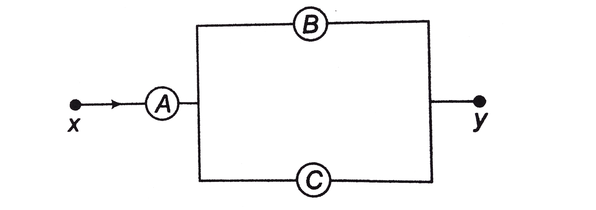
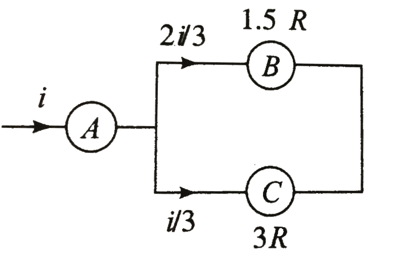
  3. A, B and C are voltmeters of resistances R, 1.5R and 3R respectively. ...

    Text Solution

    |

  4. A milliammeter of range 10 mA and resistance 9 Omega is joined in a ci...

    Text Solution

    |

  5. A candidate connects a moving coil voltmeter V, a moving coil ammeter ...

    Text Solution

    |

  6. If a shunt 1//10 of the coil resistance is applied to a moving coil ga...

    Text Solution

    |

  7. In Fig.6.59, when an ideal voltmetre is connected across 4000 Omega re...

    Text Solution

    |

  8. A voltmeter has a resistance G and range V. Calculate the resistance t...

    Text Solution

    |

  9. A galvanometer has a resistance of 3663Omega. A shunt S is connected a...

    Text Solution

    |

  10. The combined resistance of the shunt and the galvanometer is

    Text Solution

    |

  11. In Q.36, the external resistance that must be connected is series with...

    Text Solution

    |

  12. Two moving coil galvanometers 1 and 2 are with identical field magnets...

    Text Solution

    |

  13. An ammetre is obtained by shunting a 30 Omega galvanometer with a 30 O...

    Text Solution

    |

  14. Three voltmeters are connected as shown. A potential difference h...

    Text Solution

    |

  15. A constant potential difference is applied across a resistance. Consid...

    Text Solution

    |

  16. In Fig.6.61 the voltmetre and ammeter shows are ideal. Then voltmeter ...

    Text Solution

    |

  17. A potentiometer arrangement is shows in Fig. 6.62. The driver cell has...

    Text Solution

    |

  18. 50 Omega and 100 Omega resistors are connected in series. This connect...

    Text Solution

    |

  19. An ammeter gives full scale deflection when current of 1.0 A is passed...

    Text Solution

    |

  20. 100mA current gives a full scale deflection in a galvanometer of 2Omeg...

    Text Solution

    |