A
B
C
D
Text Solution
Verified by Experts
The correct Answer is:


Topper's Solved these Questions
ELECTRICAL MEASURING INSTRUMENTS
CENGAGE PHYSICS|Exercise Assertion-Reasoning|7 VideosELECTRICAL MEASURING INSTRUMENTS
CENGAGE PHYSICS|Exercise Comprehansion|15 VideosELECTRICAL MEASURING INSTRUMENTS
CENGAGE PHYSICS|Exercise Single Correct|94 VideosELECTRIC POTENTIAL
CENGAGE PHYSICS|Exercise DPP 3.5|14 VideosELECTROMAGENTIC INDUCTION
CENGAGE PHYSICS|Exercise QUESTION BANK|40 Videos
Similar Questions
Explore conceptually related problems
CENGAGE PHYSICS-ELECTRICAL MEASURING INSTRUMENTS-Multiple Correct
- A voltmeter reads the potential difference across the terminals of an ...
Text Solution
|
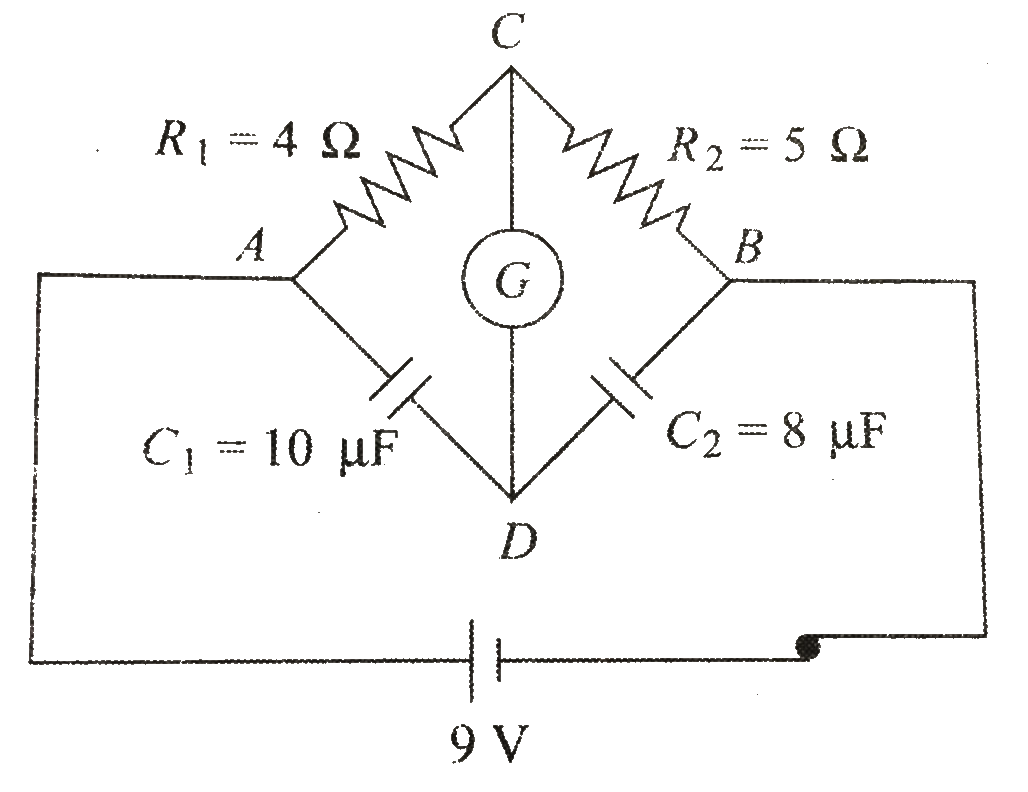
- In the circuit shows in Fig. 6.63, the cell is ideal with emf 9 V. If ...
Text Solution
|
- Figure 6.64 shows a balanced wheatstone bridge.
Text Solution
|
- Two voltmeters and two resistances are connected as shows in Fig. 6.65...
Text Solution
|
- In Fig.6.66, voltmeter is not ideal. If the voltmeter is removed from ...
Text Solution
|
- Two ideal batteries and two ammeters are arranged as shows in Fig. 6.6...
Text Solution
|
- In the above questions, if the polarity of E(2) is reversed, then
Text Solution
|