A
B
C
D
Text Solution
Verified by Experts
The correct Answer is:


Topper's Solved these Questions
MISCELLANEOUS VOLUME 3
CENGAGE PHYSICS|Exercise Multiple Correct Answer type|109 VideosMISCELLANEOUS VOLUME 3
CENGAGE PHYSICS|Exercise Assertion and Reason Type|8 VideosMECHANICAL PROPERTIES OF SOLIDS
CENGAGE PHYSICS|Exercise Question Bank|4 VideosMISCELLANEOUS VOLUME 5
CENGAGE PHYSICS|Exercise Integer|12 Videos
Similar Questions
Explore conceptually related problems
CENGAGE PHYSICS-MISCELLANEOUS VOLUME 3-True and False
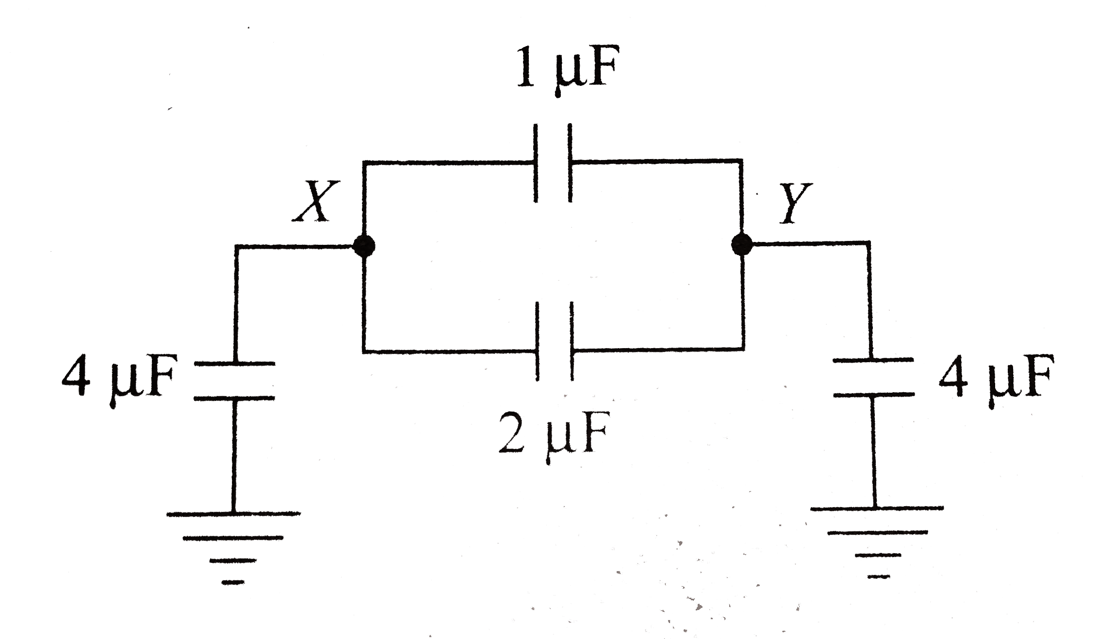
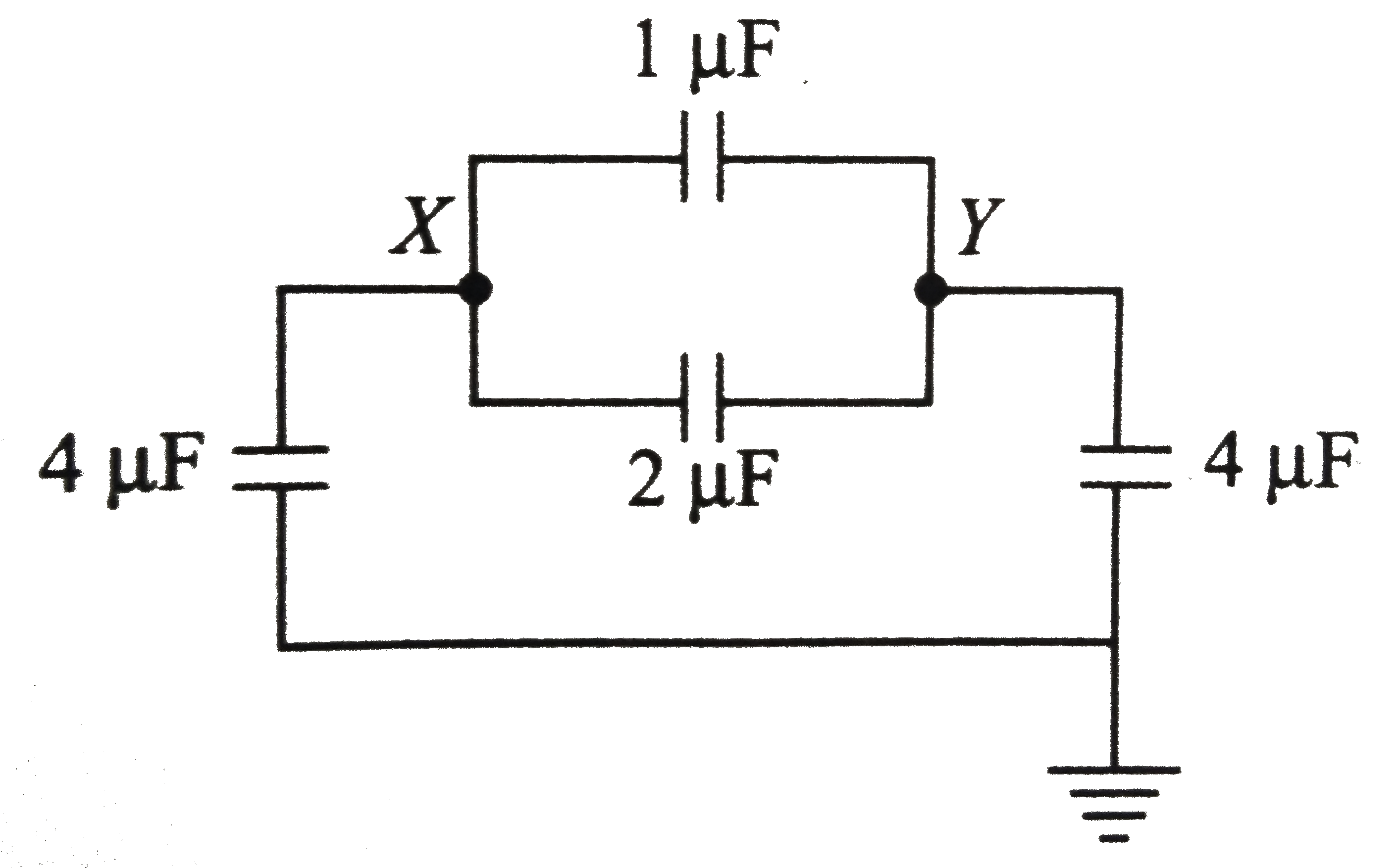
- In the circuit shown in figure, the equivalent capacitance between the...
Text Solution
|
- In an electrolytic solution the electric current is mainly due to the ...
Text Solution
|
- Determine True or False. Electrons in a conductor have no motion in th...
Text Solution
|
- The current - voltage graphs for a given metallic wire at two differen...
Text Solution
|