Home
Class 12
PHYSICS
Two capacitors of capacity 6 muF and 3 m...

Two capacitors of capacity `6 muF` and 3 muF` are charge `100 V` and `50 V` separately and connected as shown in Now all the three switches `S_(1),S_(2)`, and `S_(3)` are closed.

Which plates form an isolated system?

A

Plate 1 and plate 4 separately

B

Plate 2 and plate 3 separately

C

Plate 1 and plate 4 jointly

D

Plate 2 and plate 3 jointly

Text Solution

Verified by Experts

The correct Answer is:
D


Plates 2 and 3 are joined together and they are neither connected to any of the terminals of the battery nor to any other source of charge. So, they jointly form an isolated system. Before closing the switches, charge are shown in Fig. After closing the switch let q charge goes from battery. Then charge on each will increase by q.
Applying Kirchhoff's voltage law, we get
`200-((600+q)/(6))-((150+q)/(3))=0`
or `q=100muC`
so charge on `6muF` capacitor will be `70muC` and `3muF` capacitor will be `250muC` from all the switches `100muC` of charge will flow.
Promotional Banner

Topper's Solved these Questions

  • MISCELLANEOUS VOLUME 3

    CENGAGE PHYSICS|Exercise Interger Answer type|20 Videos
  • MISCELLANEOUS VOLUME 3

    CENGAGE PHYSICS|Exercise Fill in the blanks|10 Videos
  • MISCELLANEOUS VOLUME 3

    CENGAGE PHYSICS|Exercise Assertion and Reason Type|8 Videos
  • MECHANICAL PROPERTIES OF SOLIDS

    CENGAGE PHYSICS|Exercise Question Bank|4 Videos
  • MISCELLANEOUS VOLUME 5

    CENGAGE PHYSICS|Exercise Integer|12 Videos

Similar Questions

Explore conceptually related problems

Two capacitros of capacity 6 mu F are charged to 100 V and 50 V separately and connected as shown. Now all the three switches S_(1), S_(2) and S_(3) are closed. Charges on both the capacitors in steady state will be (on 6 mu F first)

Two capacitros of capacity 6 mu F are charged to 100 V and 50 V separately and connected as shown. Now all the three switches S_(1), S_(2) and S_(3) are closed. Suppose q_(1), q_(2) and q_(3) be the magnitudes of charge flown from switches S_(1), S_(2) and S_(3) after they closed. Then

In the circuit shown in figure C_(1)= 1mu F and C_(2) = 2 mu F . The capacitor C_(1) is charged to 100 V and the capacitor C_(2) is charged to 20 V . After charging then are connected as shown. When the switches S_(1),S_(2) and S_(3) are closed, the charged flowing through S_(1) is .

Two capacitors of capacitance 2muF and 5muF are charged to a potential difference 100V and 50 V respectively and connected such that the positive plate of one capacitor is connected to the negative plate of the other capacitor after the switch is closed, the initial current in the circuit is 50 mA. the total resistance of the connecting wires is (in Ohm):

CENGAGE PHYSICS-MISCELLANEOUS VOLUME 3-Comprehension Type
  1. Three concentric spherical conductors A, B, and C of radii r, 2R, and ...

    Text Solution

    |

  2. Three concentric spherical conductors A, B, and C of radii r, 2R, and ...

    Text Solution

    |

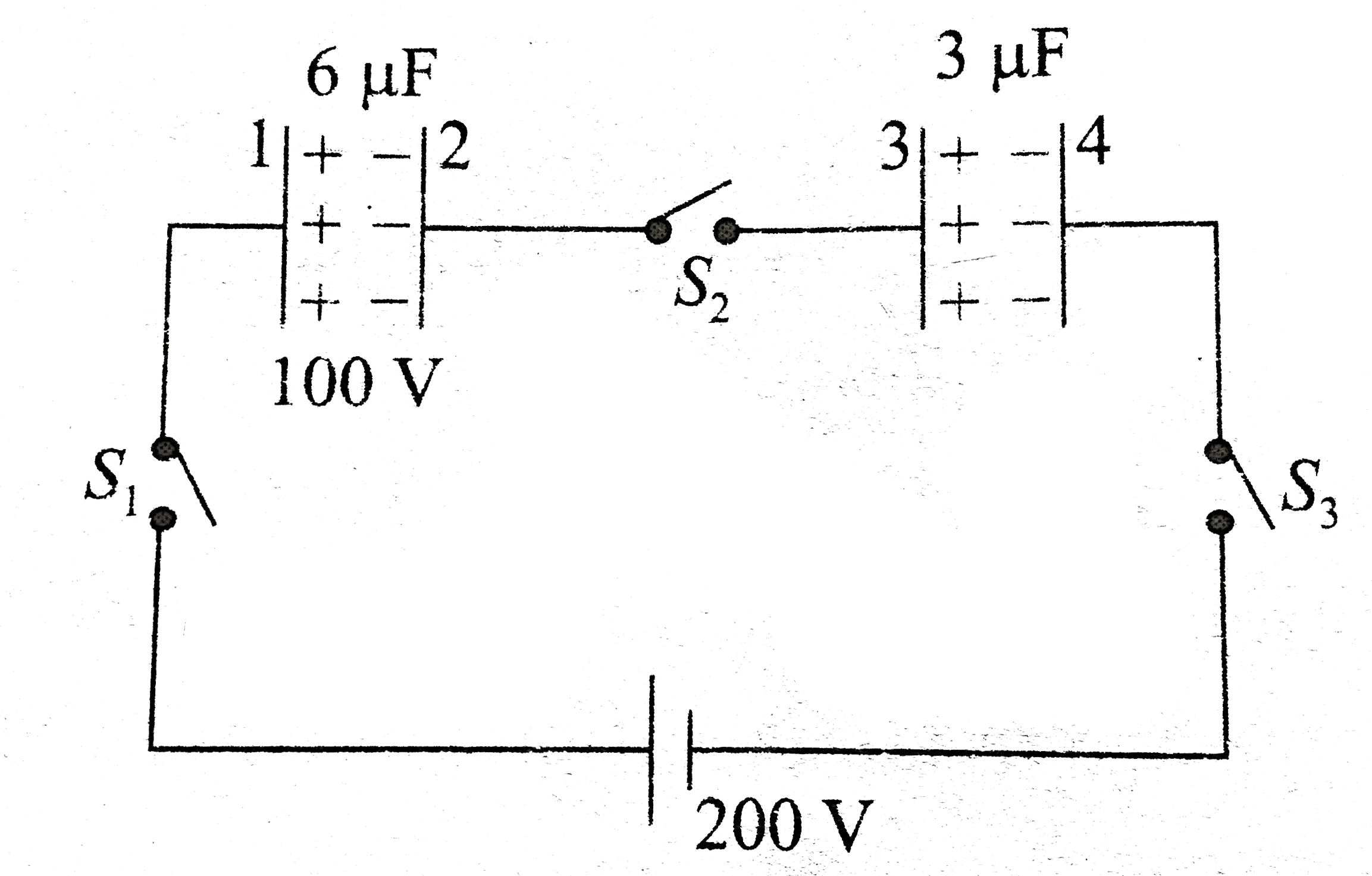
  3. Two capacitors of capacity 6 muF and 3 muF are charge 100 V and 50 V s...

    Text Solution

    |

  4. Two capacitor of capacity 6 muF and 3muF are charged to 100 V and 50 V...

    Text Solution

    |

  5. Two capacitor of capacity 6 muF and 3muF are charged to 100 V and 50 V...

    Text Solution

    |

  6. A charged particle is suspended at the center of two thin concentric s...

    Text Solution

    |

  7. A charged particle is suspended at the centre of two thin concentric s...

    Text Solution

    |

  8. A charged particle is suspended at the center of two thin concentric s...

    Text Solution

    |

  9. Capacitor C3 in the circuit is a variable capacitor (its capacitance c...

    Text Solution

    |

  10. Capacitor C3 in the circuit is a variable capacitor (its capacitance c...

    Text Solution

    |

  11. Capacitor C3 in the circuit is a variable capacitor (its capacitance c...

    Text Solution

    |

  12. In a region , an electric field E = 10NC^(-1) making an angle of theta...

    Text Solution

    |

  13. In a region , an electric field E = 10NC^(-1) making an angle of theta...

    Text Solution

    |

  14. Two circular rings A and B each of radius a = 30 cm are placed coaxial...

    Text Solution

    |

  15. Two circular rings A and B each of radius a = 30 cm are placed coaxial...

    Text Solution

    |

  16. Figure shows four plates each of plate area A and separated between pl...

    Text Solution

    |

  17. Figure shows four plates each of plate area A and separated between pl...

    Text Solution

    |

  18. Figure shows four plates each of plate area A and separated between pl...

    Text Solution

    |

  19. Three capacitors C1,C2,andC3 of capacitance 1muF, 2muF, and 3muF, resp...

    Text Solution

    |

  20. Three capacitors C1,C2,andC3 of capacitance 1muF, 2muF, and 3muF, resp...

    Text Solution

    |