A
B
C
D
Text Solution
Verified by Experts
The correct Answer is:


Similar Questions
Explore conceptually related problems
Recommended Questions
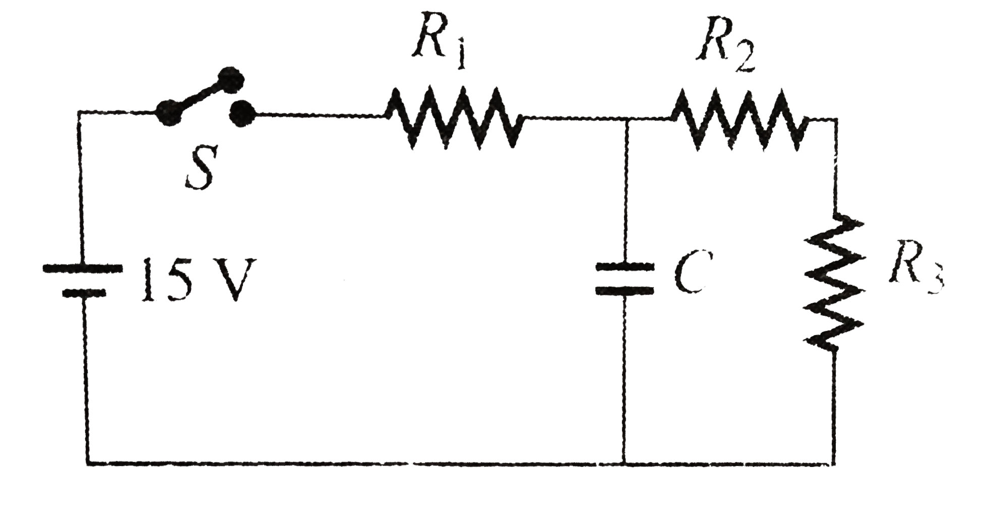
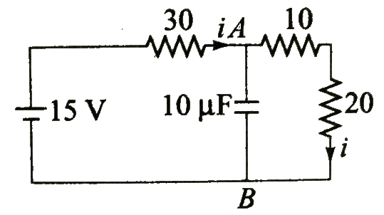
- Figure shows a battery with emf 15 V in a circuit with R1 = 30Omega, R...
Text Solution
|
- In the circuit shown , the batteries have emf E1 = E2= 1V , E3 = 2.5 V...
Text Solution
|
- Figure shows a battery with emf 15 V in a circuit with R1 = 30Omega, R...
Text Solution
|
- In the connection shown in the figure, initially the switch K is open ...
Text Solution
|
- In the connection shown in the figure, initially the switch K is open ...
Text Solution
|
- The figure below shown a battery with emf 15 V in a circuit with R(1) ...
Text Solution
|
- In R1 = 10 Omega, R2 = 40 Omega and R3 = 30 Omega, R4 = 20 Omega, R5 =...
Text Solution
|
- The circuit consists of two resistors (of resistance R(1) = 20 Omega a...
Text Solution
|
- The circuit consists of two resistors (of resistance R(1) = 20 Omega a...
Text Solution
|