A
B
C
D
Text Solution
Verified by Experts
The correct Answer is:


Similar Questions
Explore conceptually related problems
Recommended Questions
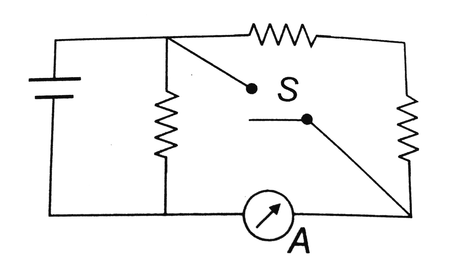
- In the circuit shown, the reading of the Ammter is doulbed after the s...
Text Solution
|
- Each of the resistors shown in figure has a resistances of 10(Omega)an...
Text Solution
|
- In the circuit shown, the reading of the Ammter is doulbed after the s...
Text Solution
|
- In the circuit shown in figure the reading of ammeter is the same with...
Text Solution
|
- In the circuit shown in figure-3.388, each ammeter has coil resistance...
Text Solution
|
- In the circuit as shown in figure , the reading of ammeter (ideal) in ...
Text Solution
|
- In the circuit shown in Fig.4.20 both the ammeter and the cell have ne...
Text Solution
|
- A voltmeter has a resistance of 50 Omega is connected across a cell of...
Text Solution
|
- Six cells each of e.m.f. 2 V and internal resistance 0.1Omega are conn...
Text Solution
|