Home
Class 12
PHYSICS
Two identical conductors P and Q are pla...

Two identical conductors `P` and `Q` are placed on two friction less rails `R` and `S` in a uniform magnetic field directed into the plane. If `P` is moved in the direction shown in figure with a constant speed, then rod `Q`

A

(a) will be attracted toward `P`

B

(b) will be repelled away from `P`

C

(c ) will remain stationary

D

(d) may be repelled away or attracted toward `P`

Text Solution

Verified by Experts

The correct Answer is:
A

(a) From Lenz's law if one rod is moved away from the second rod then the secon rod will be attrected towards the first rod so as oppose the change influx.
Promotional Banner

Topper's Solved these Questions

  • ELECTROMAGNETIC INDUCTION

    CENGAGE PHYSICS|Exercise Exercises Multiple Correct|23 Videos
  • ELECTROMAGNETIC INDUCTION

    CENGAGE PHYSICS|Exercise Exercises Asserton - Reasoning|8 Videos
  • ELECTROMAGNETIC INDUCTION

    CENGAGE PHYSICS|Exercise Exercises Subjective|13 Videos
  • ELECTROMAGENTIC INDUCTION

    CENGAGE PHYSICS|Exercise QUESTION BANK|40 Videos
  • ELECTRON,PHONTS,PHOTOELECTRIC EFFECT & X-RAYS

    CENGAGE PHYSICS|Exercise dpp 3.3|15 Videos

Similar Questions

Explore conceptually related problems

Two idential conductors P and Q are placed on two frictionless rails R and S in a uniform magnetic field directed into the plane. If P is moved in the direction shown in figure with a constant speed, then rod Q

The counductor AD moves to the right in a uniform magnetic field directed into the plane of the paper.

A thin, uniform rod with negligible mass and length 0.200m is attached to the floor by a frictionless hinge at point P (as shown in fig) A horizontal spring with force constant k=4.80Nm^-1 connects the other end of the rod to a vertical wall. The rod to a vertical wall. The rod is in a uniform magnetic field B=0.340T directed into the plane of the figure. There is current I=6.50 A in the rod, in the direction shown. Calculate the torque due to the magnetic force on the rod, for an axis at P.

The loop shown moves with a velocity v in a uniform magnetic field of magnitude B , directed into the paper. The potential differene between point P and Q is e. Then

A conductor rod AB moves parallel to X-axis in a uniform magnetic field, pointing in the positive Z-direction. The end A of the rod gets-

A straight horizontal conductor PQ of length l, and mass_ m slides down on two smooth conducting fixed parallel rails, set inclined at an angle 9 to the horizontal as shown in figure-5.30. The top end of the bar are connected with a capacitor of capacitance C. The system is placed in a uniform magnetic field, in the direction perpendicular to the inclined plane formed by the rails as shown in figure. If the resistance of the bars and the sliding conductor are negligible calculate the acceleration of sliding conductor as a function of time ifit is released from rest at t= 0

a copper rod of mass m slides under gravity on two smooth parallel rails with separation I and set at an angle of theta with the horiziontal at the bottom rails are joined by resistance R. There is a uniform magnetic field B normal to the plane of the rails as shown in the figure The terminal speed of the copper rod is :

A conducting rod of length l slides at constant velocity v on two parallel conducting rails, placed in a uniform and constant magnetic field B perpendicular to the plane of the rails as shown in Fig.3.49. A resistance R is connected between the two ends of the rails. (a) Idenify the cause which produces change in magnetic flux. (b) Identify the direction of current in the loop. ( c) Determine the emf induced in the loop. (d) Compute the electric power dissipated in the resistor. (e) Calcualte the mechenical power required to pull the rod at a cinstant velovity.

Statement I: A resistance R is connected between the two ends of the parallel smooth conducting rails. A conducting rod lies on these fixed horizontal rails and a uniform constant magnetic field B exists perpendicular to the plane of the rails as shown in Fig. if the rod is given a velocity upsilon and released as shown in Fig. 3.188, it will stop after some time. the total work done by magnetic field negative. Statement II: If force acts opposite to direction of velocity its work done is negative.

CENGAGE PHYSICS-ELECTROMAGNETIC INDUCTION-Exercises Single Correct
  1. An inducatane L and a resistance R are connected in series with a batt...

    Text Solution

    |

  2. A uniform magnetic field of induction B is confined to a cylindrical r...

    Text Solution

    |

  3. AB is a resistanceless conducting rod which forms a diameter of a cond...

    Text Solution

    |

  4. AB and CD are fixed conducting smooth rails placed in a vertical plane...

    Text Solution

    |

  5. A metallic ring of radius r with a uniform metallic spoke of negligibl...

    Text Solution

    |

  6. The current generator ig, shown in , sends a constant current I throu...

    Text Solution

    |

  7. A rod of length L rotates in the form of a conical pendulum with an An...

    Text Solution

    |

  8. A magnetic field induction is changing in magnitude in a region at a c...

    Text Solution

    |

  9. The magnetic field in a region is given by vec(B)=B(0)(1+(x)/(a))hat(k...

    Text Solution

    |

  10. A conductor AB of length l moves in x y plane with velocity vec(v) = v...

    Text Solution

    |

  11. A line charge lambda per unit length is pasted uniformly on to the wir...

    Text Solution

    |

  12. A flexible wire loop in the shape of a circle has a radius that grows ...

    Text Solution

    |

  13. A conducting wire of length l and mass m is placed on two inclined rai...

    Text Solution

    |

  14. Three identical coils A,B and C carrying currents are placed co-axiall...

    Text Solution

    |

  15. A conducting ring of radius r and resistance R rolls on a horizintal s...

    Text Solution

    |

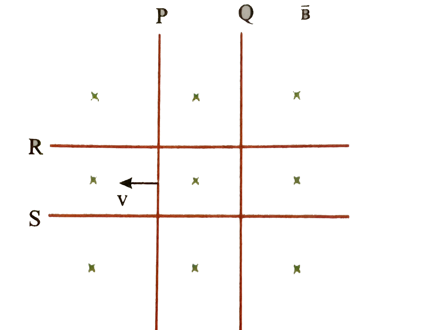
  16. Two identical conductors P and Q are placed on two friction less rails...

    Text Solution

    |

  17. In the circuit shown in Fig. A conducting wire HE is moved with a cons...

    Text Solution

    |

  18. A conducting rod PQ of length l = 2m is moving at a speed of 2m s^(-1)...

    Text Solution

    |

  19. A metallic wire is folded to form a square loop a side 'a'. It carries...

    Text Solution

    |

  20. There is a horizontal cylindrical uniform but time-varying nagnetic fi...

    Text Solution

    |