Home
Class 12
PHYSICS
In LR circuit (shown in figure), current...

In LR circuit (shown in figure), current is lagging by `pi/3` in phase with applied voltage, then select correct alternative:

A

`L=10/(sqrt(3)pi)H,i=10A`

B

`L=10/(pi)H,i=5A`

C

`L=10/(sqrt(3)pi) H,i=5A`

D

`L=(sqrt(3))/(10 pi)H,i=5A`

Text Solution

Verified by Experts

`(X_(L))/R=sqrt(3)rArr x_(L)=Rsqrt(3)`
`i=100/(sqrt((10sqrt(3))^(2)+(10)^(2)))=5A`
`L=(10sqrt(3))/(100pi)=(sqrt(3))/(10 pi) H`
Promotional Banner

Topper's Solved these Questions

  • NUCLEAR PHYSICS

    RESONANCE|Exercise Advanced level solutions|16 Videos
  • SEMICONDUCTORS

    RESONANCE|Exercise Exercise 3|88 Videos

Similar Questions

Explore conceptually related problems

In the circuit shown in figure current in the circuit is

In the following circuit the current is in phase with the applied voltage. Therefore, the current in the circuit and the frequency of the source voltage respectively, are

In the LCR circuit shown in figure (a) current will lead the voltage (2) rms value of current in 20 A (3) power factor of the circuit is (1)/(sqrt(2)) (4) voltage drop across resistance is 100 V

When an alternating voltage of 220 V is applied across a device P , a current of 0.25 A flows through the circuit and it leads the applied voltage by a angle pi/2 radian. When the same voltage source is connected across another device Q , the same current is observed in the circuit but in phase with the applied voltage. What is the current when the same source is connected across a series combination of P and Q ?

An alternating voltage of frequency f is applied across a series LCR circuit.Le f_(r) be the resonance frequency for the circuit.Will the current in the circuit lag, lead or remain in phase with the applied voltage when (i) f gt f_(r) ,(ii) f lt f_(r) ? Explain your answer in each case.

The current in the LCR circuit shown in the figure is observed to lead the voltage in phase. Without making any other change in the circuit, a capacitor, of capacitance C_0 is (appropriately) joined to the capacitor C. This results in making the current, in the joined to the capacitor C. This results in making the current, in the modified' circuit, flow in phase with the applied voltage. Draw a diagram of the modified circuit and obtain an expression of C_0 in terms of Omega , L and C.

An LCR circuit is connected to a source of alternating current. At resonance, the applied voltage and the current flowing through the circuit will have a phase difference of

In the LCR circuit shown in figure unknown resistance and alternating voltage source are connected.When swith S is closed then there is a phase difference of pi/4 between current and applied voltage and voltage across resister is 100/sqrt2 V .When switch is open current and applied voltage are in same phase.Neglecting resistance of connecting wire answer the following questions : Peak voltage of applied voltage sources is:

RESONANCE-REVISION DPP-All Questions
  1. Figure shows four situations in which a small block of mass 'm' is rel...

    Text Solution

    |

  2. A metal rod of length , moving with an angular velocity omega and velo...

    Text Solution

    |

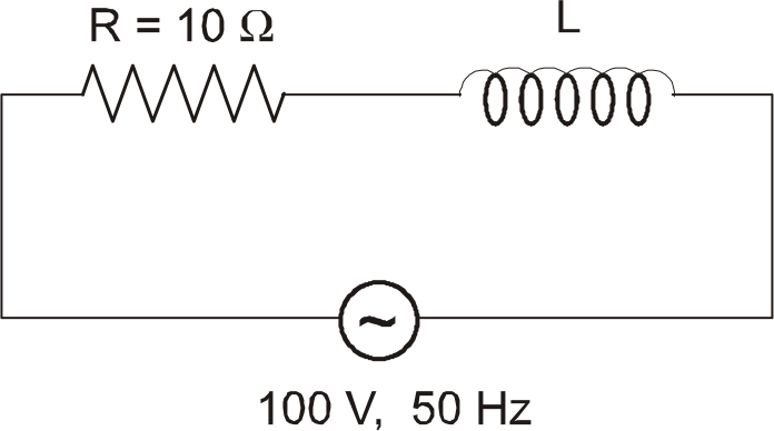
  3. In LR circuit (shown in figure), current is lagging by pi/3 in phase w...

    Text Solution

    |

  4. Three identical large plates are fixed at separation of d from each ot...

    Text Solution

    |

  5. The instantaneous potential differece between points A and B is :

    Text Solution

    |

  6. In the circuit shown, the switch is closed at t=0, the currents I1, I2...

    Text Solution

    |

  7. An LCR series circuit is in resonance with the frequency of applied ac...

    Text Solution

    |

  8. The series RLC circuit in resonance is called:

    Text Solution

    |

  9. In a series LR circuit, the voltage drop across inductor is 8 volt and...

    Text Solution

    |

  10. In the diagram shown, the wires P1Q1 and P2Q2 each of length 40cm are ...

    Text Solution

    |

  11. In a Young's double slit experiment, the separation between the slits ...

    Text Solution

    |

  12. A square loop of side 'a' is placed in x-y plane as shown in figure. I...

    Text Solution

    |

  13. In a YDSE, distance between the slits and the screen is 1m, separation...

    Text Solution

    |

  14. A rectangular loop of sides of length l and b is placed in x-y plane. ...

    Text Solution

    |

  15. Assume Earth's surface is a conductor with a uniform surface charge de...

    Text Solution

    |

  16. A series RLC circuit is connected to an ac generator. The instant at w...

    Text Solution

    |

  17. A wire shaped as a semicircle of radius a, is rotating about an acis P...

    Text Solution

    |

  18. Consider a series LCR circuit connected to an AC supply of 220V. If vo...

    Text Solution

    |

  19. If the two slits of double slit experiment were moved symmetrically ap...

    Text Solution

    |

  20. In the figure shown the key is switched on at t=0. Let l1 and l2 be th...

    Text Solution

    |