Home
Class 12
PHYSICS
In the circuit shown in fig. X(C ) = 100...

In the circuit shown in fig. `X_(C ) = 100 Omega,(X_L)=200 Omega and R=100 Omega`. The effective current through the source is

Text Solution

Verified by Experts


`I_(R)=V/R=200/100=2A`
`I'=V/(X_(L)-X_(C))=200/100 =2A`
`I=sqrt(I_(R)^(2)+I'^(2))=2sqrt(2) Amp`.
Promotional Banner

Topper's Solved these Questions

  • NUCLEAR PHYSICS

    RESONANCE|Exercise Advanced level solutions|16 Videos
  • SEMICONDUCTORS

    RESONANCE|Exercise Exercise 3|88 Videos

Similar Questions

Explore conceptually related problems

In the circuit diagram show, X_(C)=100Omega, X_(L)=200Omega,& R=100Omega

In a series L-C-R circuit X_(L)350 Omega, X_(C)=200 Omega and R = 150 Omega .

In an AC series circuit, R = 10 Omega, X_L=20Omega and XC=10Omega .Then, choose the correct options

200 V ac source is fed to series LCR circuit having X_(L)=50 Omega, X_(C )=50 Omega and R = 25 Omega . Potential drop across the inductor is

In the circuit shown in Fig. 4.19. R_(1)=100 Omega, R_(2)=R_(3)=50 Omega, R_(4)=75 Omega and E=4.75 V. Work out the equivalent resistance of the circuit and the current in each resistor.

Consider the circuit shown in fig. Assuming R_1 =2Omega = R_4, R_3 = 4Omega, current passing through the circuit if resistance R_2 is removed is (remove ground connection at point X)

In a given series LCR circuit R=4Omega, X_(L)=5Omega and X_(C)=8Omega , the current

In a series A.C. circuit , R=100Omega , X_(L)=300Omega and X_(C )=200Omega . The phase difference between the applied e.m.f. and the current will be

Consider the circuit shown in fig. Current through R_2 is zero if R_4 = 2Omega and R_3 = 4 Omega in this case

RESONANCE-REVISION DPP-All Questions
  1. In the circuit shown in figure : R = 10 Omega , L = (sqrt(3))/(10) H...

    Text Solution

    |

  2. What is the ratio of powers delivered by 20 V dc and 20 V peak ac to t...

    Text Solution

    |

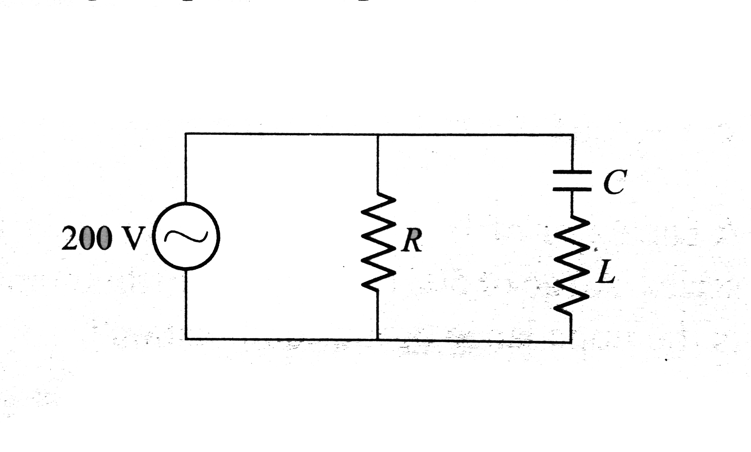
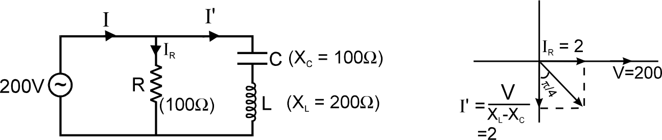
  3. In the circuit shown in fig. X(C ) = 100 Omega,(XL)=200 Omega and R=10...

    Text Solution

    |

  4. In the LR circuit the switch S was closed for a long time. The ideal c...

    Text Solution

    |

  5. In YDSE with monochromatic light, fringes are obtained on the screen ...

    Text Solution

    |

  6. Interference fringes were produced using light in a doulbe-slit experi...

    Text Solution

    |

  7. A certain transmission line (very long) is constructed from two thin m...

    Text Solution

    |

  8. A certain transmission line (very long) is constructed from two thin m...

    Text Solution

    |

  9. A certain transmission line (very long) is constructed from two thin m...

    Text Solution

    |

  10. A fan operates at 200 volt (DC) consuming 1000W when running at full s...

    Text Solution

    |

  11. A fan operates at 200 volt (DC) consuming 1000W when running at full s...

    Text Solution

    |

  12. A fan operates at 200 volt (DC) consuming 1000W when running at full s...

    Text Solution

    |

  13. Consider a conducting circular loop placed in a magentic filed as sho...

    Text Solution

    |

  14. Consider a conducting circular loop placed in a magentic filed as sho...

    Text Solution

    |

  15. Consider a conducting circular loop placed in a magentic filed as sho...

    Text Solution

    |

  16. In YDSE arrangement as shown in figure, fringes are seen on screen usi...

    Text Solution

    |

  17. In YDSE arrangement as shown in figure, fringes are seen on screen usi...

    Text Solution

    |

  18. In YDSE arrangement as shown in figure, fringes are seen on screen usi...

    Text Solution

    |

  19. Time varying magnetic filed is present in a circular region of radius ...

    Text Solution

    |

  20. Find the natural frequency of oscillation of the system as shown in fi...

    Text Solution

    |