


RESONANCE-REVISION DPP-All Questions
- Consider a conducting circular loop placed in a magentic filed as sho...
Text Solution
|
- Consider a conducting circular loop placed in a magentic filed as sho...
Text Solution
|
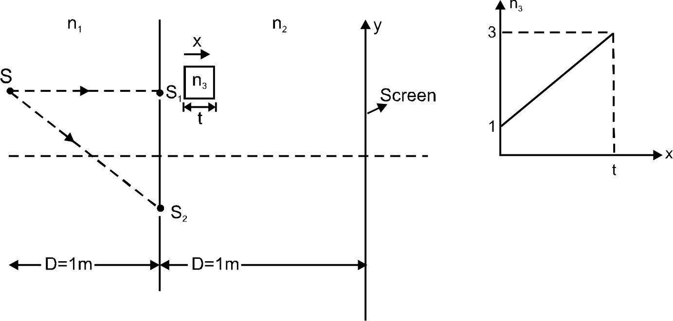
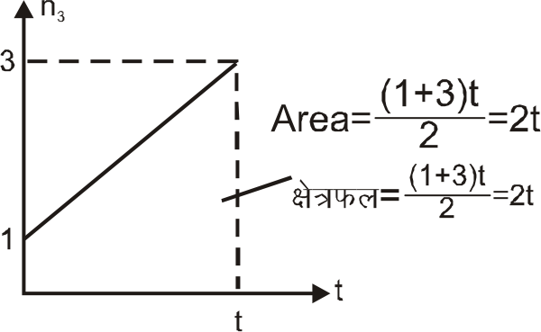
- In YDSE arrangement as shown in figure, fringes are seen on screen usi...
Text Solution
|
- In YDSE arrangement as shown in figure, fringes are seen on screen usi...
Text Solution
|
- In YDSE arrangement as shown in figure, fringes are seen on screen usi...
Text Solution
|
- Time varying magnetic filed is present in a circular region of radius ...
Text Solution
|
- Find the natural frequency of oscillation of the system as shown in fi...
Text Solution
|
- A thin uniform straight rod of mass 2 kg and length 1 m is free to rot...
Text Solution
|
- All sides of an equilateral triangle are diameter of three identical u...
Text Solution
|
- A block of dimensions lxtxh and uniform density rho(w) rests on a roug...
Text Solution
|
- An oscillation is superposition of three harmonic oscillations and dec...
Text Solution
|
- A uniform thin hemispherical shell is kept at rest and in equilibrium ...
Text Solution
|
- Find the natural frequency of the system shown in figure. The pulleys ...
Text Solution
|
- A massless stick of length L is hinged at one end and a mass m attache...
Text Solution
|
- A uniform disc of mass m is attached to a spring of spring constant k ...
Text Solution
|
- A particle is executing simple harmonic motion in a conservative force...
Text Solution
|
- Two particle of mass m each are fixed to a massless rod of length 2l ....
Text Solution
|
- Two copper balls of radius r and 2r are released at rest in a long tub...
Text Solution
|
- A uniform solid cone of mass m, base radius ‘R’ and height 2R, has a s...
Text Solution
|
- A uniform metal rod fixed at its ends of 2 mm^(2) cross-section is ...
Text Solution
|