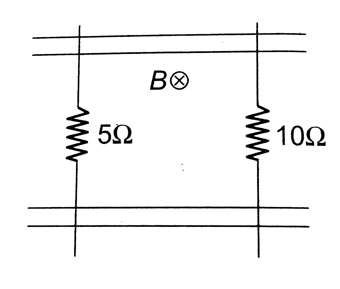
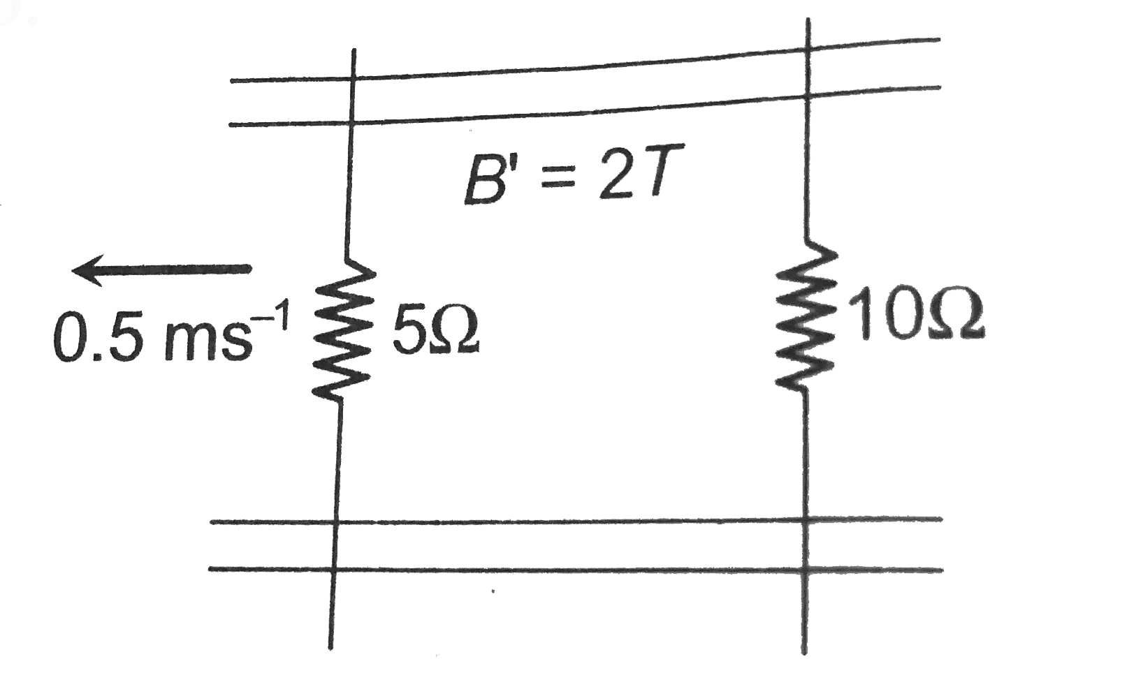
Home
Class 12
PHYSICS
A pair of parallel conducting rails lie ...

A pair of parallel conducting rails lie at right angle to a uniform magnetic field of `2.0T` as shown in the fig. two resistor `10Omega` and `5Omega` are to slide without friction along the rail. The distance between the conducting rails is `0.1m`. Then

A

Induced current `=(1)/(150)A` directed clockwise if `10Omega`
resistor is pulled to the right with speed `0.5ms^(-1)` and resistor is held fixed

B

Induced current `=(1)/(300)A` directed anti-clockwise if
`10Omega` resistor is pulled to the right with speed `0.5ms^(-1)` and `10Omega` resistor is held fixed

C

Induced current `=(1)/(300)A` directed clockwise if `5Omega`
resistor is pulled to the left at `0.5ms^(-1)` and `10Omega` resistor is held at res

D

Induced current `=(1)/(150)A` directed anti-clockwise if`5Omega`
resistor is pulled to the left at `0.5ms^(-1)` and `10Omega` resistor is held at rest

Text Solution

Verified by Experts

The correct Answer is:
D

Induced current `=(10)/(150)A` directed anti-clockwise `5Omega` resistor is pulled to the left at `0.5ms^(-1)` and `10Omega` resistor is held at rest(d) when `5Omega` resistor is pulled left at `0.5 m//sec` induced emf., in the said resistor `=e=vBl=0.5xx2xx0.1=0.1V`.
Resistor `10Omega` is at rest so induced emf in it `(e=vBl)` be zero.
Now net emf in the circuit`=0.1V`
and equivalent resistance of the circuit
`R=15Omega`
Hence current `i=(0.1)/(15)` amp `=(1)/(150)` amp
And its direction will be anti-clockwise (according to Lenz's law)
Promotional Banner

Topper's Solved these Questions

  • ELECTROMAGNETIC INDUCTION

    A2Z|Exercise Section B - Assertion Reasoning|31 Videos
  • ELECTROMAGNETIC INDUCTION

    A2Z|Exercise AIPMTNEET Questions|27 Videos
  • ELECTROMAGNETIC INDUCTION

    A2Z|Exercise Applications Of Emi|58 Videos
  • ELECTRIC POTENTIAL & CAPACITANCE

    A2Z|Exercise Section D - Chapter End Test|29 Videos
  • ELECTROMAGNETIC WAVES AND COMMUNICATION SYSTEM

    A2Z|Exercise Section D - Chapter End Test|30 Videos

Similar Questions

Explore conceptually related problems

Consider parallel conducting rails separated by a distance l. There exists a uniform magnetic field B perpendicular to the plane of the rails as shown in Fig. Two conducting wires each of length l are placed so as to slide on parallel conducting rails. One of the wires is given a velocity v_(0) parallel to the rails. Till steady state is achieved, loss in kinetic energy of the system is

Two long fixed parallel vertical conducting rails AB and CD are separated by a distance L. They are connected by resistance R and a capacitance C at two ends as shown in the figure. There is a uniform magnetic field B directed horizon- tally into the plane of the figure. A horizontal metallic bar of length L and mass m can slide without friction along the rails. The bar is released from rest at t = 0. Neglect resistance of bar and rails and also neglect the self inductance of the loop. (a) Find the maximum speed acquired by the bar after it is released. (b) Find the speed of the bar as a function of time t.

A conducting rod of length is moved at constant velocity v_(0) on two parallel, conducting, smooth, fixed rails, that are placed in a uniform constant magnetic field B perpendicular to the plane for the rails as shown in Fig. A resistance R is connected between the two ends of the rails. Then which of the following is/are correct:

A wire of length l , mass m and resistance R slides without any friction down the parallel conducting rails of negligible resistance . The rails are connected to each other at the bottom by a resistanceless rail parallel to the wire so that the wire and the rails form a closed rectangualr conducting loop. The plane of the rails makes an angle theta with the horizontal and a uniform vertical magnetic field of the inducetion B exists throughout the rregion. Find the steady state velocity of the wire.

A conducting rod of length l slides at constant velocity v on two parallel conducting rails, placed in a uniform and constant magnetic field B perpendicular to the plane of the rails as shown in Fig.3.49. A resistance R is connected between the two ends of the rails. (a) Idenify the cause which produces change in magnetic flux. (b) Identify the direction of current in the loop. ( c) Determine the emf induced in the loop. (d) Compute the electric power dissipated in the resistor. (e) Calcualte the mechenical power required to pull the rod at a cinstant velovity.

A conducting bar mass m and length l moves on two frictionless parallel conducting rails in the presence of a uniform magnetic field B_(0) directed into the paper. The bar is given an initial velocity v_(0) to the right and is released at t = 0 . The velocity of the bar as a function of time is given by

Two smooth horizontal parallel conducting rails are connected with a capacitor and a resistor at the two ends as shown. A uniform conducting rod PQ of mass 'm' and length 'l' is dragged with a constant horizontal force 'F'. The terminal velocity aquired by the conducting rod is

A rod with resistance R lies across frictionless conducting rails in a constant uniform magnetic field vecB , as shown in the following figure. Assume the rails have negligible resistance. The magnitude of the force that must be applied by a person to pull the rod to the right at constant speed v is

Figure shows a wire sliding on two parallel, conducting rails placed at a separation L . A magnetic field B exists in a direction perpendicular to the plane of the rails. What force is necessary to keep the wire moving at a constant velocity V ?

Two long parallel conducting horizontal rails are connected by a conducting wire at one end. A uniform magnetic field B (directed vertically downwards) exists in the region of space. A light uniform ring of diameter d which is practically equal to separation between the rails is placed over the rails as shown in Fig. If resistance of ring be (lambda) per unit length The force required to pull the ring with uniform velocity v is

A2Z-ELECTROMAGNETIC INDUCTION-Problems On Mixed Concepts
  1. A rectangle loop with a sliding connector of length l=1.0 m is situate...

    Text Solution

    |

  2. A metal rod of resistance 20 Omega is fixed along a diameter of a cond...

    Text Solution

    |

  3. A pair of parallel conducting rails lie at right angle to a uniform ma...

    Text Solution

    |

  4. A short magnet is allowed to fall along the axis of a horizontal metal...

    Text Solution

    |

  5. The horizontal component of the earth's magnetic field at a place is 3...

    Text Solution

    |

  6. The magnetic field in the cylindrical region shown in figure increase ...

    Text Solution

    |

  7. A metal disc of radius a rotates with a constant angular velocity omeg...

    Text Solution

    |

  8. A horizontal wire is free to slide on the vertical rails of a conducti...

    Text Solution

    |

  9. A square coil ACDE with its plane vertically is released from rest in ...

    Text Solution

    |

  10. The radius of the circular conducting loop shown in figure is R. Magne...

    Text Solution

    |

  11. A current of 2A is increasing at a rate of 4A//s through a coil of ind...

    Text Solution

    |

  12. A conducting rod PQ of length l=1.0m is moving with a uniform speed v2...

    Text Solution

    |

  13. Two conducting circular loops of radii R1 and R2 are placed in the sa...

    Text Solution

    |

  14. A circular loop of radius R, carrying current I, lies in x-y plane wit...

    Text Solution

    |

  15. Two identical circular loops of metal wire are lying on a table withou...

    Text Solution

    |

  16. Two coils have a mutual inductance 0.005 H. The current changes in the...

    Text Solution

    |

  17. A wire of length 1 m is moving at a speed of 2 ms^(-1) perpendicular t...

    Text Solution

    |

  18. An equilateral tringular loop ADC having some resistance is pulled wit...

    Text Solution

    |

  19. A coil of wire having inductance and resistance has a conducting ring ...

    Text Solution

    |

  20. A coil of inductance 8.4 mH and resistance 6 Omega is connected to a 1...

    Text Solution

    |