Home
Class 12
PHYSICS
A copper rod of mass m slides under grav...

A copper rod of mass `m` slides under gravity on two smooth parallel rails `l` distance apart set at an angle `theta` to the horizontal. At the bottom, the rails are joined by a resistance `R`.

There is a uniform magnetic field perpendicular to the plane of the rails. the terminal valocity of the rod is

A

`(mg R costheta)/(B^(2)l^(2))`

B

`(mg R sin theta)/(B^(2)l^(2))`

C

`(mg R tan theta)/(B^(2)l^(2))`

D

`(mg R cot theta)/(B^(2)l^(2))`

Text Solution

Verified by Experts

The correct Answer is:
A

Terminal velocity is attained when magnetic force is equal to `mg sin theta`
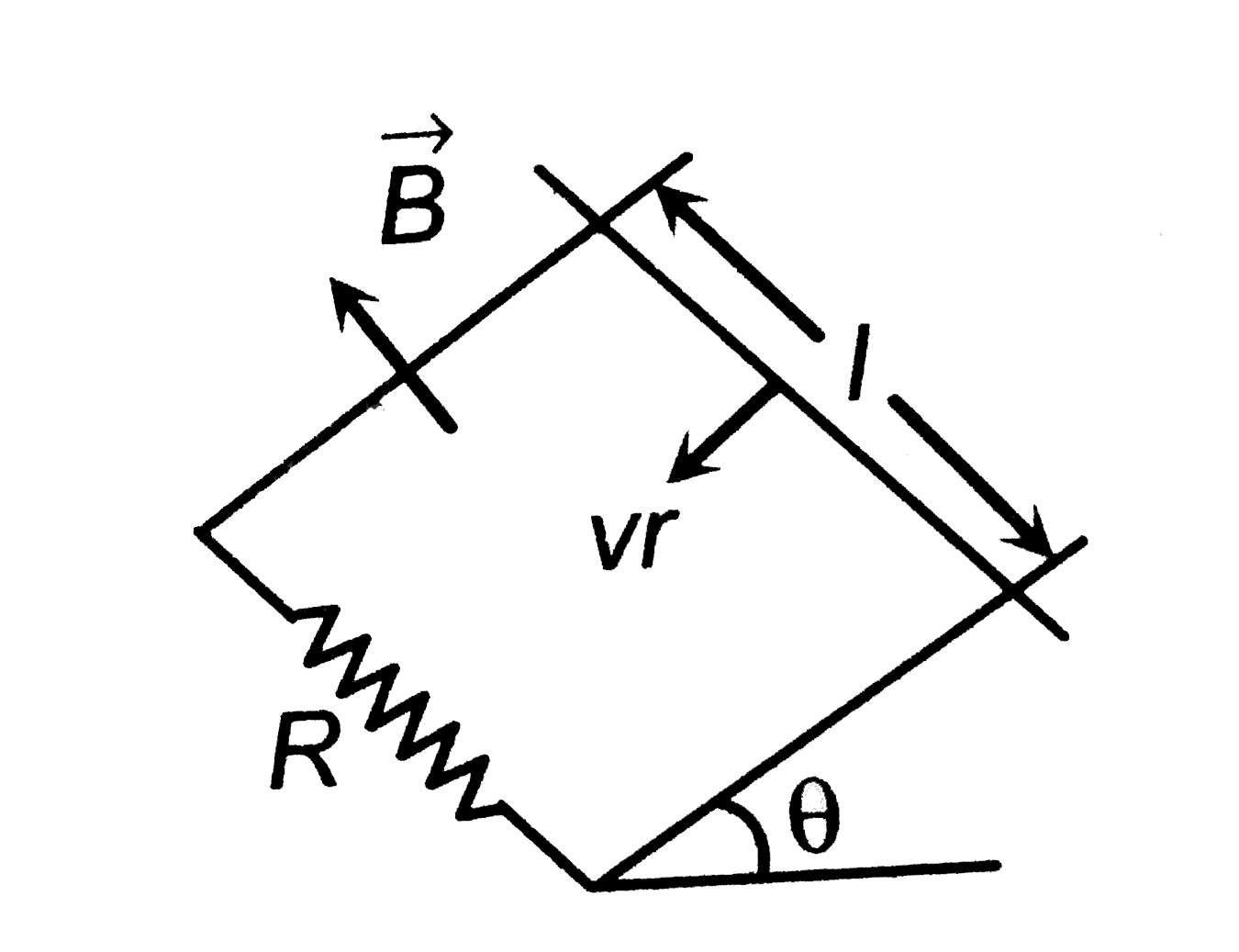
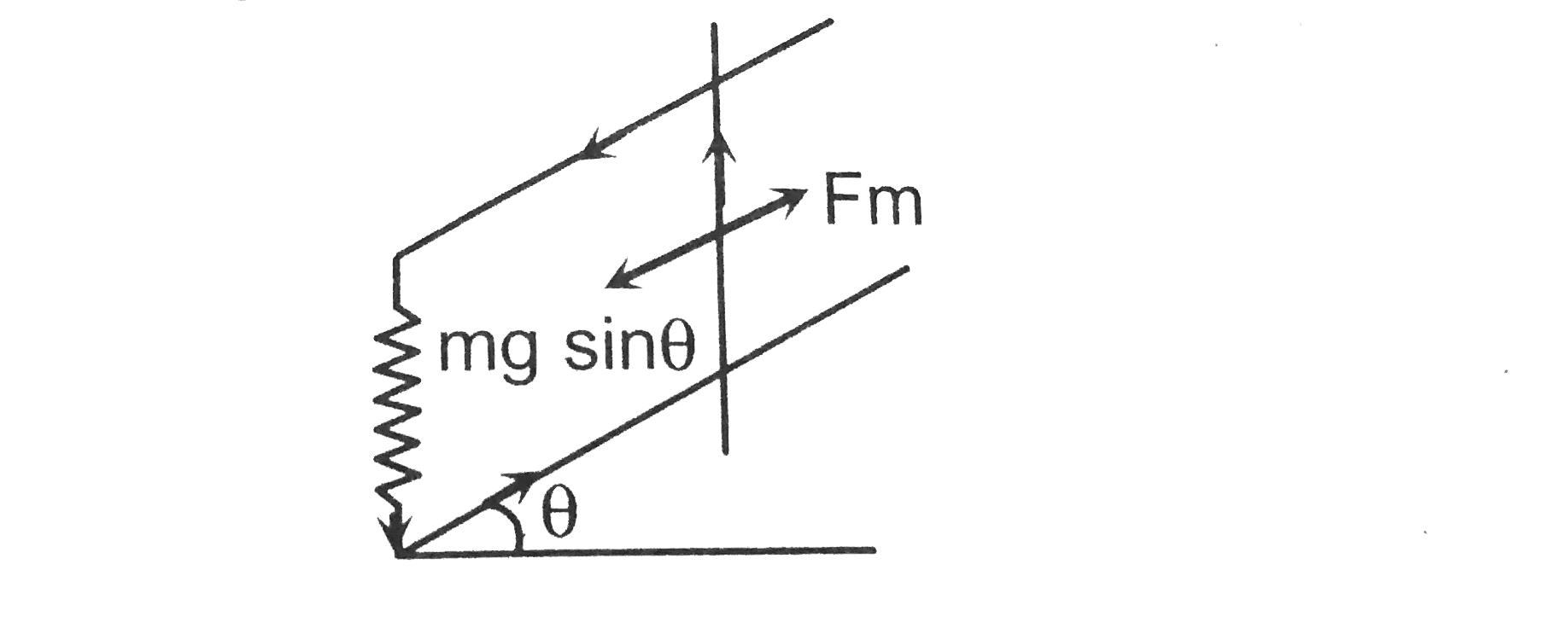
:. `F_(m)=mg sin theta`
or `ilB=mg sin theta`
or `((e)/(R ))lB=mgsintheta`
or `((Bv_(T)l))/(R )=lB=mgsintheta`
:. `v_(T)=(mgRsintheta)/(B^(2)l^(2))`
Promotional Banner

Topper's Solved these Questions

  • ELECTROMAGNETIC INDUCTION

    A2Z|Exercise Section B - Assertion Reasoning|31 Videos
  • ELECTROMAGNETIC INDUCTION

    A2Z|Exercise AIPMTNEET Questions|27 Videos
  • ELECTROMAGNETIC INDUCTION

    A2Z|Exercise Applications Of Emi|58 Videos
  • ELECTRIC POTENTIAL & CAPACITANCE

    A2Z|Exercise Section D - Chapter End Test|29 Videos
  • ELECTROMAGNETIC WAVES AND COMMUNICATION SYSTEM

    A2Z|Exercise Section D - Chapter End Test|30 Videos

Similar Questions

Explore conceptually related problems

a copper rod of mass m slides under gravity on two smooth parallel rails with separation I and set at an angle of theta with the horiziontal at the bottom rails are joined by resistance R. There is a uniform magnetic field B normal to the plane of the rails as shown in the figure The terminal speed of the copper rod is :

A conductor rod AB of mass m slides without friction over two long conducting rails separated by a distance (Fig) At the left end the raidls are interconnected by a resistance R . The system is located in a unifrom magnetic fileld perpendicular to the plane of the loop. At the moment t = 0 the rod AB starts moving to the right with an initial velocity v_(0) . Neglecting the resistances of the rails and the rod AB , as wellas the self -indcuctance, find: (a) the distance covered by the rod until it comes to a standsill, (b) the amount of heat generated in the resitance R during this process.

Shows a rod of length l and resistance r moving on two rails shorted by a resistance R . A uniform magnetic field B is present normal to the plane of rod and rails. Show the electrical equivalence of each branch.

A rod of mass m and radius R rest on two parallel rails that are distance l apart and have a length L . The rod carries a current I ( in the direction shown ) and rolls along the rails without slipping. A uniform magnetic field B is directed perpendicular to the rod and the rails. If it starts from rest, wat is the speed of the rod as it leaves the rails ?

A vertical ring of radius r and resistance on R falls vertically. It is in contact with two vertical rails which are joined at the top. The rails are without friction and resistance. There is a horizontal uniform, magnetic field of magnitude B perpendicular to the plane of the ring and the rails. When the speed of the ring is v , the current in the section PQ is

Two thick rods AB, CD are placed parallel to each other at a distance l . their ends are joined to a resistance R . A magnetic field of induction B is applied perpendicular to the plane contaning the rods. If the rods are vertical, the terminal uniform velocity of the rod PQ of mass m is given by

A straight horizontal conductor PQ of length l, and mass_ m slides down on two smooth conducting fixed parallel rails, set inclined at an angle 9 to the horizontal as shown in figure-5.30. The top end of the bar are connected with a capacitor of capacitance C. The system is placed in a uniform magnetic field, in the direction perpendicular to the inclined plane formed by the rails as shown in figure. If the resistance of the bars and the sliding conductor are negligible calculate the acceleration of sliding conductor as a function of time ifit is released from rest at t= 0

Two parallel long smooth conducting rails separated by a distance l are connected by a movable conducting connector of mass m . Terminals of the rails are connected by the resistor R and the capacitor C as shown in figure. A uniform magnetic field B perpendicular to the plane of the rail is switched on. The connector is dragged by a constant force F . Find the speed of the connector as a function of time if the force F is applied at t = 0 . Also find the terminal velocity of the connector.

A2Z-ELECTROMAGNETIC INDUCTION-Problems On Mixed Concepts
  1. An equilateral tringular loop ADC having some resistance is pulled wit...

    Text Solution

    |

  2. A coil of wire having inductance and resistance has a conducting ring ...

    Text Solution

    |

  3. A coil of inductance 8.4 mH and resistance 6 Omega is connected to a 1...

    Text Solution

    |

  4. An inductor of 2 henry and a resistance of 10 ohms are connected in se...

    Text Solution

    |

  5. A short-circuited coil is placed in a time-varying magnetic field. Ele...

    Text Solution

    |

  6. An electric motor runs a D.C. source of e.m.f. 200 V and draws a curre...

    Text Solution

    |

  7. The approximate formula expressing the formula of mutual inductance of...

    Text Solution

    |

  8. The length of a thin wire required to manufacture a solenoid of length...

    Text Solution

    |

  9. Magnetic flux linked with a stationary loop of resistance R varies wit...

    Text Solution

    |

  10. A physicist works in a laboratory where the magnetic field is 2T. She ...

    Text Solution

    |

  11. Figure show a square loop of side 0.5 m and resistance 10Omega. The ma...

    Text Solution

    |

  12. A copper rod of mass m slides under gravity on two smooth parallel rai...

    Text Solution

    |

  13. Shown in the figure is a circular loop of radius r and resistance R. A...

    Text Solution

    |

  14. A highly conucting ring of radius R is perpendicular to and concentric...

    Text Solution

    |

  15. How much length of a very thin wire is required to obtain a solenoid o...

    Text Solution

    |

  16. What is the mutual inductance of a two-loop system as shown with centr...

    Text Solution

    |

  17. Plane figures made of thin wires of resistance R=50 milliohm//metre ar...

    Text Solution

    |

  18. A rectangular loop with a sliding connector of length l=1.0 m is situa...

    Text Solution

    |

  19. A Conducting ring of radius 1 meter is placed in an uniform magnetic f...

    Text Solution

    |

  20. A uniform but time varying magnetic field B(t) exist in a circular reg...

    Text Solution

    |