A
B
C
D
Text Solution
Verified by Experts
The correct Answer is:


Topper's Solved these Questions
ELECTROMAGNETIC INDUCTION & ALTERNATING CURRENT
PRADEEP|Exercise JEE Mains Ad..(Multiple Choice Question)|1 VideosELECTROMAGNETIC INDUCTION & ALTERNATING CURRENT
PRADEEP|Exercise Multiple Choice Questions|1 VideosELECTROMAGNETIC INDUCTION & ALTERNATING CURRENT
PRADEEP|Exercise Value Based Questions|2 VideosDUAL NATURE OF RADIATION AND MATTER
PRADEEP|Exercise Exercise|191 VideosELECTROMAGNETIC WAVES
PRADEEP|Exercise II Focus multiple choice question|5 Videos
Similar Questions
Explore conceptually related problems
PRADEEP-ELECTROMAGNETIC INDUCTION & ALTERNATING CURRENT-Exercise
- The network shown in the figure is a part of complete circuit. What is...
Text Solution
|
- A wire of mass m and length I can freely slide on a pair of parallel, ...
Text Solution
|
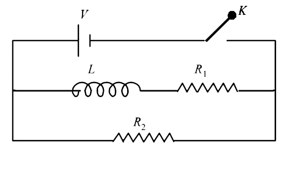
- In the circuit shown below, the key K is closed at t =0. The current t...
Text Solution
|
- A resistor 'R' and 2(mu)F capacitor in series is connected through a s...
Text Solution
|
- LetC be the capacitance of a capacitor discharging through a resistor ...
Text Solution
|
- An inductor (L =0.03 H) and a resistor (R = 0.15k(Omega)) are connecte...
Text Solution
|
- A 150 ohm resistor and inductor of inductance L are connected in serie...
Text Solution
|
- In a circuit, the instantaneous values of alternating current and volt...
Text Solution
|
- In an ac circuit , L = (0.4)/(pi) H and R = 30 Omega. If the circuit h...
Text Solution
|
- In an ac circuit , an alternating voltage e = 200 sqrt2 sin 100 t volt...
Text Solution
|
- An ideal coil of 10H is connected in series with a resistance of 5(Ome...
Text Solution
|
- In the circuit shown if Fig. the switch S is closed at time t = 0. The...
Text Solution
|
- An inductor (L = 100 mH), a resistor (R = 100 (Omega)) and a battery (...
Text Solution
|
- An inductor of inductance L=400 mH and resistor of resistance R(1) = 2...
Text Solution
|
- The figure shows an experimental plot discharging of a capacitor in an...
Text Solution
|
- In an LCR circuit as shown below both switches are open initially. Now...
Text Solution
|
- In the circuit shown here, the point 'C' is kept connected to point 'A...
Text Solution
|
- A pure resistive circuit element X when connected to an a.c. supply of...
Text Solution
|
- In the circuit shown in figureure the AC source gives a voltage V=20co...
Text Solution
|
- In the circuit shown in Fig. currrent through the battery at t = 0 and...
Text Solution
|