Home
Class 12
PHYSICS
In an LCR circuit as shown below both sw...

In an LCR circuit as shown below both switches are open initially. Now switch `S_(1)` kept open. (q is charge on the capacitor and `tau = RC` is Capacitive time constant). Which of the following statement is correct?

A

Work done by the battery is half of the energy dissipated in the resistor

B

At `t = tau, q = CV//2`

C

At `t = 2 tau, q = CV (1 - e^(-2))`

D

At `t = (tau)/(2), q = CV (1 - e^(-1))`.

Text Solution

Verified by Experts

The correct Answer is:
C

In the figure, when switch `S_(1)` is closed and switch `S_(2)` is kept open, the condenser gets charged through resistance. At any time t, the charge acquired by the condenser is
`Q = Q_(0) (1 - e^(-t//RC))`, where `Q_(0) = CV` and `RC = tau`
At `t = 2 tau, Q = Q_(0) (1 - e^(-2tau//tau)) = CV (1 - e^(-2))`
Choice (c ) is correct.
Promotional Banner

Topper's Solved these Questions

  • ELECTROMAGNETIC INDUCTION & ALTERNATING CURRENT

    PRADEEP|Exercise JEE Mains Ad..(Multiple Choice Question)|1 Videos
  • ELECTROMAGNETIC INDUCTION & ALTERNATING CURRENT

    PRADEEP|Exercise Multiple Choice Questions|1 Videos
  • ELECTROMAGNETIC INDUCTION & ALTERNATING CURRENT

    PRADEEP|Exercise Value Based Questions|2 Videos
  • DUAL NATURE OF RADIATION AND MATTER

    PRADEEP|Exercise Exercise|191 Videos
  • ELECTROMAGNETIC WAVES

    PRADEEP|Exercise II Focus multiple choice question|5 Videos

Similar Questions

Explore conceptually related problems

A capacitor is charged to a potential of V_(0) . It is connected with an inductor through a switch S. The switch is closed at time t=0. Which of the following statement(s) is/are correct?

In the circuit shown in the figure, if switches S_(1) and S_(2) have been closed for a long time, then charge on the capacitor.

For the circuit shown in figure below, At t = 0, switch is closed, the initial current through resistor and final charge on capacitor are

Three capacitors (of capacitances C , 2C and 3C ) and three resistors (of resistance R , 2R and 3R ) are connected with a battery and switch S as shown in the figure. When switch S is open, charges on the capacitors are shown. Switch S is closed at t=0 sec . The time constant of the circuit will be

In the circuit shown below, the switch S is connected to position P for a long time so that the charge on the capacitor become q1 mu C . The S is switched to psition Q. After a long time, the charge on the capacitor is q2 mu C . The magnitude of q1 is

In the circuit shown below, the switch S is connected to position P for a long time so that the charge on the capacitor become q1 mu C . The S is switched to psition Q. After a long time, the charge on the capacitor is q2 mu C . The magnitude of q2 is

In the given circuit the capacitor (C) may be charged through resistance R by a battery V by closing switch (S_1) . Also when (S_1) is opend and (S_2) is closed the capacitor is connected in series with inductor (L). At the start, the capicitor was uncharged. when switch (S_1) is closed and (S_2) is kept open, the time constant of this circuit is tau . which of the following is correct

The circuit was in the shown state from a long time. Now the switch S is closed. The charged that flows through the switch is

In the circuit shown, the reading of ammeter when switch S is open and when switch S is closed respectively are

PRADEEP-ELECTROMAGNETIC INDUCTION & ALTERNATING CURRENT-Exercise
  1. An inductor of inductance L=400 mH and resistor of resistance R(1) = 2...

    Text Solution

    |

  2. The figure shows an experimental plot discharging of a capacitor in an...

    Text Solution

    |

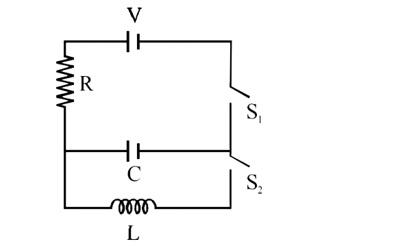
  3. In an LCR circuit as shown below both switches are open initially. Now...

    Text Solution

    |

  4. In the circuit shown here, the point 'C' is kept connected to point 'A...

    Text Solution

    |

  5. A pure resistive circuit element X when connected to an a.c. supply of...

    Text Solution

    |

  6. In the circuit shown in figureure the AC source gives a voltage V=20co...

    Text Solution

    |

  7. In the circuit shown in Fig. currrent through the battery at t = 0 and...

    Text Solution

    |

  8. In the given circuit, Fig., the reading of voltmeter V(1) and V(2) 300...

    Text Solution

    |

  9. The natural frequency of the circuit shows in Fig. is

    Text Solution

    |

  10. An L-C-R series circuit with 100Omega resistance is connected to an AC...

    Text Solution

    |

  11. In a certain circuit current changes with time accroding to i=2sqrt(t)...

    Text Solution

    |

  12. An ac source of angular frequency omega is fed across a resistor R and...

    Text Solution

    |

  13. A pure resistive circuit element X when connected peak current of 5 A ...

    Text Solution

    |

  14. In series LR circuit, X(L) = 3 R. Now a capacitor with X(C ) = R is ad...

    Text Solution

    |

  15. In a circuit L, C and R are connected in series with an alternating vo...

    Text Solution

    |

  16. A condenser of 250 mu F is connected in parallel to a coil of inductan...

    Text Solution

    |

  17. When an ac source of emfe=E(0) sin (100 t) is connected across a circu...

    Text Solution

    |

  18. In a coil of resistance 100 Omega , a current is induced by changing t...

    Text Solution

    |

  19. An AC voltage source of variable angular frequency omega and fixed amp...

    Text Solution

    |

  20. In a series LCR circuit R= 200(Omega) and the voltage and the frequenc...

    Text Solution

    |